Quickstart: Grow a Plant
Page Info
Audience: Beginner
Prerequisites: basic Julia,
PlantGeom,MultiScaleTreeGraph,CairoMakieTime: 10 minutes
Output: Loop-driven growth with explicit geometry rebuild
We'll need a few packages to build and visualize the plant model. Add them to your environment if needed, then load them:
using PlantGeom
using MultiScaleTreeGraph
using GeometryBasics
using Colors
using CairoMakie
Defining Prototypes
Before growing the plant, we first define the basic shapes used for each organ. In this example, we create a simple cylindrical stem and a leaf shape. The leaf is defined with a PointMapPrototype and a LaminaMidribMap, which let us control features such as leaf curvature and tip droop. These settings can also be overridden for each individual leaf during growth, so the leaves do not all have the same shape. PlantGeom provides the built-in lamina mesh and midrib map used here.
# Build the reference meshes:
stem = RefMesh("stem", GeometryBasics.mesh(GeometryBasics.Cylinder(Point(0,0,0), Point(1,0,0), 0.5)), RGB(0.48, 0.36, 0.25))
leaf = lamina_refmesh("leaf"; length=1.0, max_width=1.0, material=RGB(0.19, 0.61, 0.29))
prototypes = Dict(:Internode => RefMeshPrototype(stem), :Leaf => PointMapPrototype(leaf; defaults=(base_angle_deg=42.0, bend=0.3, tip_drop=0.08), intrinsic_shape=p -> LaminaMidribMap(base_angle_deg=p.base_angle_deg, bend=p.bend, tip_drop=p.tip_drop)))
Dict{Symbol, AbstractMeshPrototype} with 2 entries:
:Leaf => PointMapPrototype{RefMesh{String, Mesh{3, Float64, TriangleFace…
:Internode => RefMeshPrototype{RefMesh{String, Mesh{3, Float64, TriangleFace{…We can visualize the prototypes to make sure they look right:
f = Figure(size=(600, 300))
ax1 = Axis3(f[1, 1], title="Stem Prototype", perspectiveness=0.5)
mesh!(ax1, stem.mesh, color=stem.material)
ax2 = Axis3(f[1, 2], title="Leaf Prototype", perspectiveness=0.5)
mesh!(ax2, leaf.mesh, color=leaf.material)
f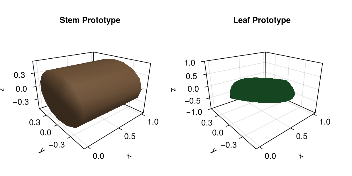
Keep in mind that prototypes are only templates for geometry generation. What matters here is their shape. Their final dimensions are normalized in the prototype and later set from node attributes during growth.
Next, we create the first node, labeled :Plant, with an edge label of :/. This node serves as the starting point for the growth process.
Note
By default, this tutorial uses graph-theory terms rather than botanical ones unless stated otherwise:
The root node is the first node in the graph, not the root of the plant.
A node is a graph node that can represent any plant organ, such as a stem or a leaf, and not the botanical term "node".
plant = Node(NodeMTG(:/, :Plant, 1, 1))/ 1: PlantWe can now take the first growth step by emitting an internode from the plant node. This creates a new node labeled :Internode, attaches it to the plant node with an edge labeled :/, and stores attributes such as length and width for later geometry generation.
Then, with the first internode in place, we can enter a growth loop that emits new internodes and leaves step by step. In this example, we build a simple axis with 8 internodes and 7 leaves, with one leaf attached to each internode after the first. We also assign attributes to each leaf, including length, width, thickness, phyllotaxy, and y-insertion angle. In addition, we use prototype_overrides to vary the bend and tip-drop parameters from one leaf to the next, which creates a gradual change in leaf shape along the axis.
The resulting code is as follows:
let
    axis = emit_internode!(plant; link=:/, length=0.18, width=0.022)

    for i in 2:8
        axis = emit_internode!(axis; index=i, length=0.17 * 0.95^(i - 2), width=0.021 * 0.93^(i - 2))
        emit_leaf!(
            axis;
            index=i,
            offset=0.8 * axis[:Length],
            length=0.22 + 0.018i,
            width=0.032 + 0.003i,
            thickness=0.01 + 0.0015i,
            phyllotaxy=isodd(i) ? 0.0 : 180.0,
            y_insertion_angle=54.0,
            prototype=:Leaf,
            prototype_overrides=(bend=0.12 + 0.06i, tip_drop=0.02i)
        )
    end
end

plant
/ 1: Plant
└─ / 2: Internode
└─ < 3: Internode
├─ + 4: Leaf
└─ < 5: Internode
├─ + 6: Leaf
└─ < 7: Internode
├─ + 8: Leaf
└─ < 9: Internode
├─ + 10: Leaf
└─ < 11: Internode
├─ + 12: Leaf
└─ < 13: Internode
├─ + 14: Leaf
└─ < 15: Internode
└─ + 16: LeafOnce the plant structure has been created, we can materialize its geometry by calling rebuild_geometry! with the plant graph and the prototypes. This function traverses the graph, generates geometry for each node from its attributes and prototype, and stores the result in the node attributes. Keeping geometry generation separate from topology and attribute updates makes the growth process easier to understand and debug:
rebuild_geometry!(plant, prototypes)/ 1: Plant
└─ / 2: Internode
└─ < 3: Internode
├─ + 4: Leaf
└─ < 5: Internode
├─ + 6: Leaf
└─ < 7: Internode
├─ + 8: Leaf
└─ < 9: Internode
├─ + 10: Leaf
└─ < 11: Internode
├─ + 12: Leaf
└─ < 13: Internode
├─ + 14: Leaf
└─ < 15: Internode
└─ + 16: LeafFinally, we can visualize the generated plant with plantviz, which renders the geometry stored in the node attributes. Note that we also pass a figure size to improve readability from this document, but it is not necessary in a normal Julia session:
plantviz(plant, figure=(size=(980, 700),))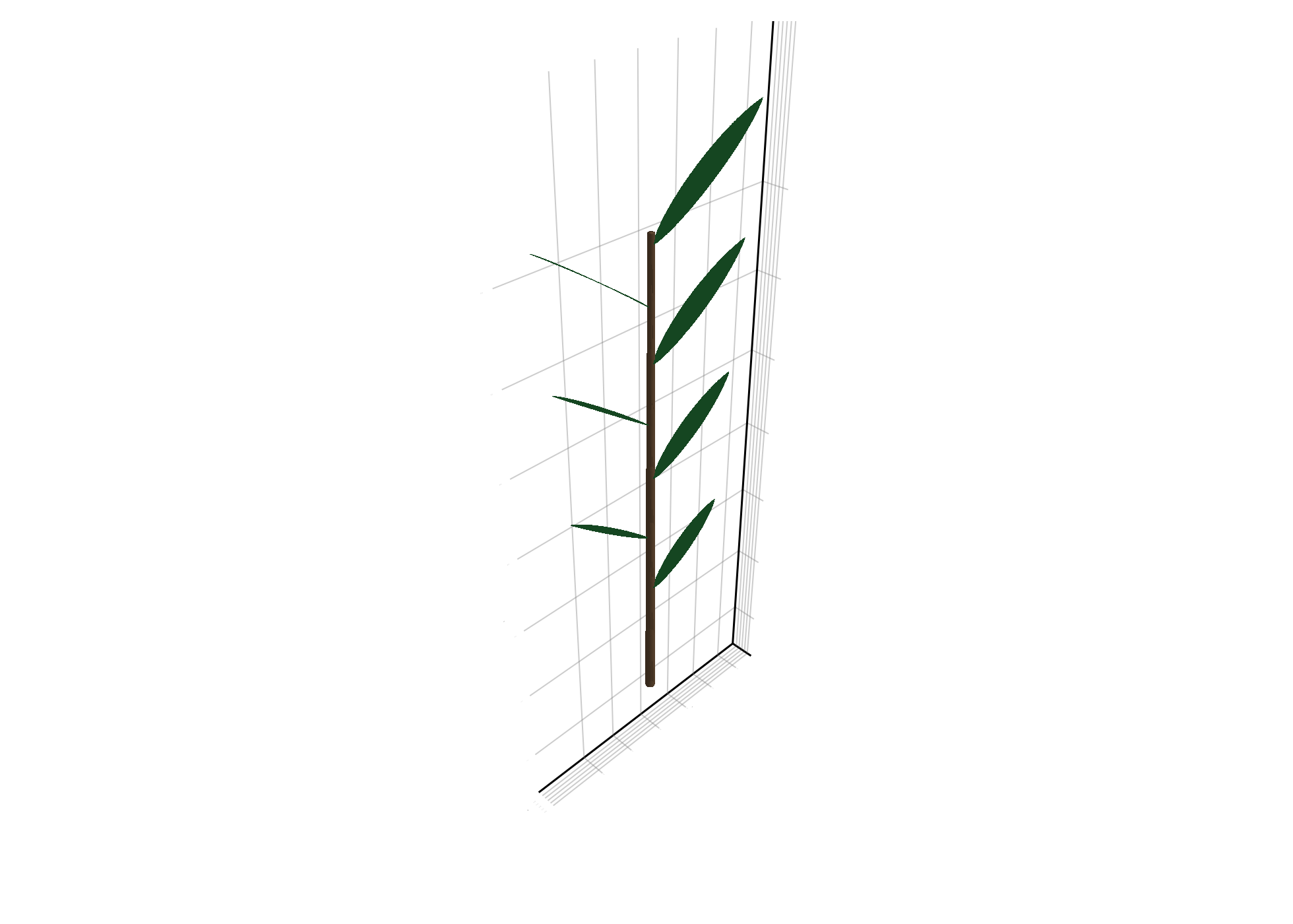
Summary
The growth process has the following stages:
| Stage | What happens |
|---|---|
emit_internode! | creates a new stem node and writes growth attributes |
emit_leaf! | creates a leaf node attached to current stem node |
prototype_overrides | changes shape parameters per leaf instance |
rebuild_geometry! | materializes all node geometry once at the end |
plantviz(...) | renders the generated plant |
The growth API lets us build complex plant structures by iteratively updating graph topology and node attributes while keeping geometry generation explicit. By defining prototypes with shape parameters, we can produce a wide range of organ shapes and control them during growth.
The growth API is not meant to cover every possible growth process, but it provides a flexible framework for building custom growth loops and organ emission patterns. You can define your own growth functions, create new prototypes, and implement more complex growth dynamics as needed. For a more advanced example of growth and geometry generation, see the VPalm module in XPalm.
Copy-Paste Example
If you want to reproduce this example quickly, paste the following code into a Julia session with the required packages loaded:
using PlantGeom, MultiScaleTreeGraph, GeometryBasics, Colors, CairoMakie
CairoMakie.activate!()

stem = RefMesh("stem", GeometryBasics.mesh(GeometryBasics.Cylinder(Point(0,0,0), Point(1,0,0), 0.5)), RGB(0.48, 0.36, 0.25))
leaf = lamina_refmesh("leaf"; length=1.0, max_width=1.0, material=RGB(0.19, 0.61, 0.29))
prototypes = Dict(:Internode => RefMeshPrototype(stem), :Leaf => PointMapPrototype(leaf; defaults=(base_angle_deg=42.0, bend=0.3, tip_drop=0.08), intrinsic_shape=p -> LaminaMidribMap(base_angle_deg=p.base_angle_deg, bend=p.bend, tip_drop=p.tip_drop)))

plant = Node(NodeMTG(:/, :Plant, 1, 1)); axis = emit_internode!(plant; link=:/, length=0.18, width=0.022)
for i in 2:8
    axis = emit_internode!(axis; index=i, length=0.17 * 0.95^(i - 2), width=0.021 * 0.93^(i - 2))
    emit_leaf!(axis; index=i, offset=0.8 * axis[:Length], length=0.22 + 0.018i, width=0.032 + 0.003i, thickness=0.01 + 0.0015i, phyllotaxy=isodd(i) ? 0.0 : 180.0, y_insertion_angle=54.0, prototype=:Leaf, prototype_overrides=(bend=0.12 + 0.06i, tip_drop=0.02i))
end
rebuild_geometry!(plant, prototypes)
plantviz(plant, figure=(size=(980, 700),))
How It Works
The growth loop only updates topology and node attributes. rebuild_geometry! is called once, so geometry generation stays explicit and easy to debug.
Troubleshooting
If your leaf shapes do not change, verify the leaf prototype key and override names.
If plotting is slow, keep geometry rebuild explicit and lower its frequency.