Growth API
Page Info
Audience: Beginner to Intermediate
Prerequisites: basic Julia and MTG reconstruction concepts
Time: 20 minutes
Output: explicit Julia growth loops and controlled geometry rebuilds
The Growth API is the high-level API for building plant structure step by step in Julia.
It is designed for simulations where you want to:
create new organs over time
update their measured or simulated attributes
decide exactly when geometry should be regenerated
This is the key idea:
create nodes and write attributes with
emit_internode!,emit_leaf!,emit_phytomer!update attributes with
grow_length!,grow_width!,set_growth_attributes!call
rebuild_geometry!when you want geometry to be materialized from those attributes
So the Growth API is topology + attributes first, and geometry second.
What The Growth API Is
The Growth API is not a fixed growth model. It is a small set of Julia functions that let you write your own growth logic explicitly.
For example, this is the intended style:
while t <= nsteps
    if should_emit_new_leaf(t)
        emit_leaf!(...)
    end

    grow_length!(...)
    set_growth_attributes!(...)

    if should_export_geometry(t)
        rebuild_geometry!(...)
    end
end
That style is useful because:
it is easy to debug
it stays close to the simulation logic you actually want
geometry generation cost stays under your control
Quick Chooser
| If you want to... | Use |
|---|---|
| Add one internode | emit_internode! |
| Add one leaf | emit_leaf! |
| Add one internode + one leaf together | emit_phytomer! |
| Increase length over time | grow_length! |
| Increase width or thickness over time | grow_width! |
| Set any node attribute explicitly | set_growth_attributes! |
| Generate/update geometry from current attributes | rebuild_geometry! |
Terminology
In this page:
an internode can follow or branch from its bearer
a leaf always branches from its bearer
a phytomer is one internode plus one leaf emitted together
a prototype is the reusable geometry rule used to create 3D geometry from node attributes
Approaches
PlantGeom proposes two main workflows for building and simulating plants. The first is purely structural: you build the topology and set attributes in a loop, then call rebuild_geometry! once at the end. The second workflow uses PlantSimEngine to couple structure and function. Both are defined below.
Structure-only mode
The structure only mode is ideal when you want to build plant structure in Julia without coupling to a full simulation engine. In this case, you write a growth loop that creates topology and sets attributes, and then call rebuild_geometry! once at the end to generate geometry. The main functions to use are detailed in the table below:
| Function | What it does |
|---|---|
emit_internode!(parent; kwargs...) | adds an :Internode child node and writes growth attributes |
emit_leaf!(parent; kwargs...) | adds a :Leaf child node and writes growth attributes |
emit_phytomer!(parent; internode=..., leaf=...) | emits one internode and one leaf in one call |
grow_length!(x; delta) | increments :Length |
grow_width!(x; delta, thickness_policy=...) | increments :Width and optionally :Thickness |
set_growth_attributes!(x; kwargs...) | writes arbitrary attributes on the node |
rebuild_geometry!(mtg, prototypes; ...) | generates geometry from current node attributes |
PlantSimEngine-coupled mode
The structure-function mode is ideal when you want to simulate growth modulated by function (e.g. stresses). This mode is intended to be called from a PlantSimEngine model. In this case, you can use the same emit_* and grow_* functions, but pass Status objects instead of MTG nodes. This lets you keep PlantGeom responsible for topology and geometry generation, while PlantSimEngine handles status initialization and function coupling.
Note
This mode is a work in progress and may require some manual setup. If you want to use PlantSimEngine, we recommend starting with the structure-only mode to get familiar with the API, and then integrating PlantSimEngine once you are comfortable with the growth functions.
Complete Example: Build A Plant In A Loop
This example is fully runnable as shown. It builds a simple axis with one leaf per internode, then materializes geometry.
1. Load packages
using PlantGeom
using MultiScaleTreeGraph
using GeometryBasics
using Colors
using CairoMakie

CairoMakie.activate!()
2. Define the geometry prototypes
We define:
one cylindrical internode prototype
one leaf prototype based on a normalized lamina and a parametric midrib map
stem_ref = RefMesh(
    "stem",
    GeometryBasics.mesh(
        GeometryBasics.Cylinder(
            Point(0.0, 0.0, 0.0),
            Point(1.0, 0.0, 0.0),
            0.5,
        ),
    ),
    RGB(0.48, 0.36, 0.25),
)

leaf_ref = lamina_refmesh(
    "leaf";
    length=1.0,
    max_width=1.0,
    n_long=36,
    n_half=7,
    material=RGB(0.19, 0.61, 0.29),
)

prototypes = Dict(
    :Internode => RefMeshPrototype(stem_ref),
    :Leaf => PointMapPrototype(
        leaf_ref;
        defaults=(base_angle_deg=42.0, bend=0.30, tip_drop=0.08),
        intrinsic_shape=params -> LaminaMidribMap(
            base_angle_deg=params.base_angle_deg,
            bend=params.bend,
            tip_drop=params.tip_drop,
        ),
    ),
)
Dict{Symbol, AbstractMeshPrototype} with 2 entries:
:Leaf => PointMapPrototype{RefMesh{String, Mesh{3, Float64, TriangleFace…
:Internode => RefMeshPrototype{RefMesh{String, Mesh{3, Float64, TriangleFace{…We can visualize the reference meshes used in the prototypes to make sure they look right:
f = Figure(size=(600, 300))
ax1 = Axis3(f[1, 1], title="Stem reference mesh", perspectiveness=0.5)
plantviz!(ax1, stem_ref)
ax2 = Axis3(f[1, 2], title="Leaf reference mesh", perspectiveness=0.5)
plantviz!(ax2, leaf_ref)
f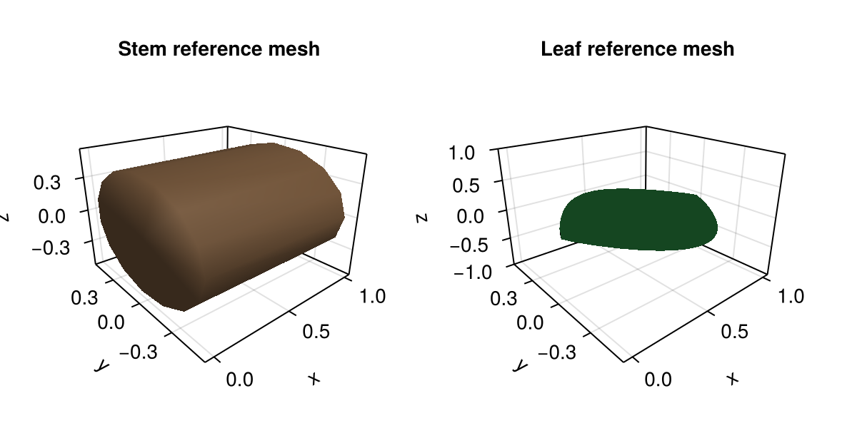
Note that the stem prototype just uses the reference mesh as is, while the leaf prototype uses the reference mesh along with the LaminaMidribMap to define how the final leaf geometry will be shaped based on attributes such as base_angle_deg, bend, and tip_drop.
The important idea here is:
the prototypes are reusable templates
final organ size still comes from node attributes such as
Length,Width, andThickness
3. Create the root node
plant = Node(NodeMTG(:/, :Plant, 1, 1))/ 1: PlantThis :Plant node is the graph root. It is not itself an organ geometry in this example. It is the parent from which we emit organs.
4. Emit organs in a growth loop
We first emit one internode, then keep extending the axis. Each new leaf receives:
a position along the bearer with
offsetdimensions (
length,width,thickness)insertion orientation (
phyllotaxy,y_insertion_angle)leaf-shape overrides through
prototype_overrides
plant = let p = plant
    axis = emit_internode!(
        p;
        index=1,
        link=:/,
        length=0.18,
        width=0.022,
    )

    for i in 2:8
        axis = emit_internode!(
            axis;
            index=i,
            length=0.17 * 0.95^(i - 2),
            width=0.021 * 0.93^(i - 2),
            y_euler=2.0 * sin(i / 3),
        )

        emit_leaf!(
            axis;
            index=i,
            offset=0.80 * axis[:Length],
            length=0.22 + 0.018 * i,
            width=0.032 + 0.003 * i,
            thickness=0.010 + 0.0015 * i,
            phyllotaxy=isodd(i) ? 0.0 : 180.0,
            y_insertion_angle=54.0,
            prototype=:Leaf,
            prototype_overrides=(bend=0.12 + 0.06 * i, tip_drop=0.02 * i),
        )
    end

    p
end

plant
/ 1: Plant
└─ / 2: Internode
└─ < 3: Internode
├─ + 4: Leaf
└─ < 5: Internode
├─ + 6: Leaf
└─ < 7: Internode
├─ + 8: Leaf
└─ < 9: Internode
├─ + 10: Leaf
└─ < 11: Internode
├─ + 12: Leaf
└─ < 13: Internode
├─ + 14: Leaf
└─ < 15: Internode
└─ + 16: LeafAt this point:
the topology exists
the attributes exist
geometry has not been rebuilt yet
You can inspect the graph state before geometry generation:
first_internode = first(children(plant))
first_leaf = first(filter(n -> symbol(n) == :Leaf, descendants(plant; self=true)))

(
    first_internode_length=first_internode[:Length],
    first_leaf_symbol=symbol(first_leaf),
    first_leaf_prototype=first_leaf[:GeometryPrototype],
    first_leaf_overrides=first_leaf[:GeometryPrototypeOverrides],
)
(first_internode_length = 0.18, first_leaf_symbol = :Leaf, first_leaf_prototype = :Leaf, first_leaf_overrides = (bend = 0.24, tip_drop = 0.04))5. Rebuild geometry explicitly
rebuild_geometry!(plant, prototypes)/ 1: Plant
└─ / 2: Internode
└─ < 3: Internode
├─ + 4: Leaf
└─ < 5: Internode
├─ + 6: Leaf
└─ < 7: Internode
├─ + 8: Leaf
└─ < 9: Internode
├─ + 10: Leaf
└─ < 11: Internode
├─ + 12: Leaf
└─ < 13: Internode
├─ + 14: Leaf
└─ < 15: Internode
└─ + 16: LeafThis is the step that turns the stored attributes into actual geometry in node[:geometry].
6. Visualize the result
plantviz(plant, figure=(size=(980, 700),))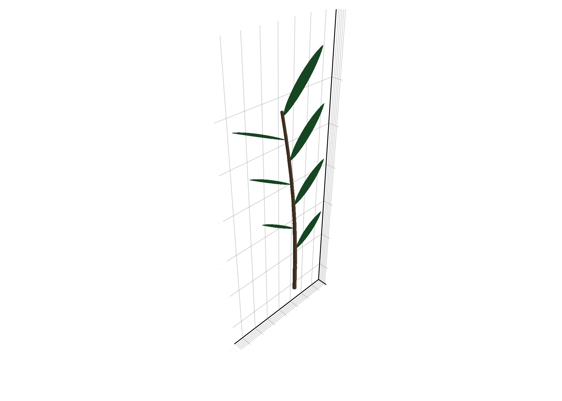
Mutating Existing Organs
The Growth API also lets you modify an existing organ after emission.
Update length and width
target_internode = children(plant)[1]

grow_length!(target_internode; delta=0.04)
grow_width!(target_internode; delta=0.004, thickness_policy=:follow_width)

(
    Length=target_internode[:Length],
    Width=target_internode[:Width],
    Thickness=target_internode[:Thickness],
)
(Length = 0.22, Width = 0.026, Thickness = 0.026)Update arbitrary attributes
target_leaf = first(filter(n -> symbol(n) == :Leaf, descendants(plant; self=true)))

set_growth_attributes!(
    target_leaf;
    leaf_stage=:adult,
    age=3,
    GeometryPrototypeOverrides=(bend=0.75, tip_drop=0.20),
)

(
    leaf_stage=target_leaf[:leaf_stage],
    age=target_leaf[:age],
    overrides=target_leaf[:GeometryPrototypeOverrides],
)
(leaf_stage = :adult, age = 3, overrides = (bend = 0.75, tip_drop = 0.2))After mutating attributes, rebuild geometry again:
rebuild_geometry!(plant, prototypes)
plantviz(plant, figure=(size=(980, 700),))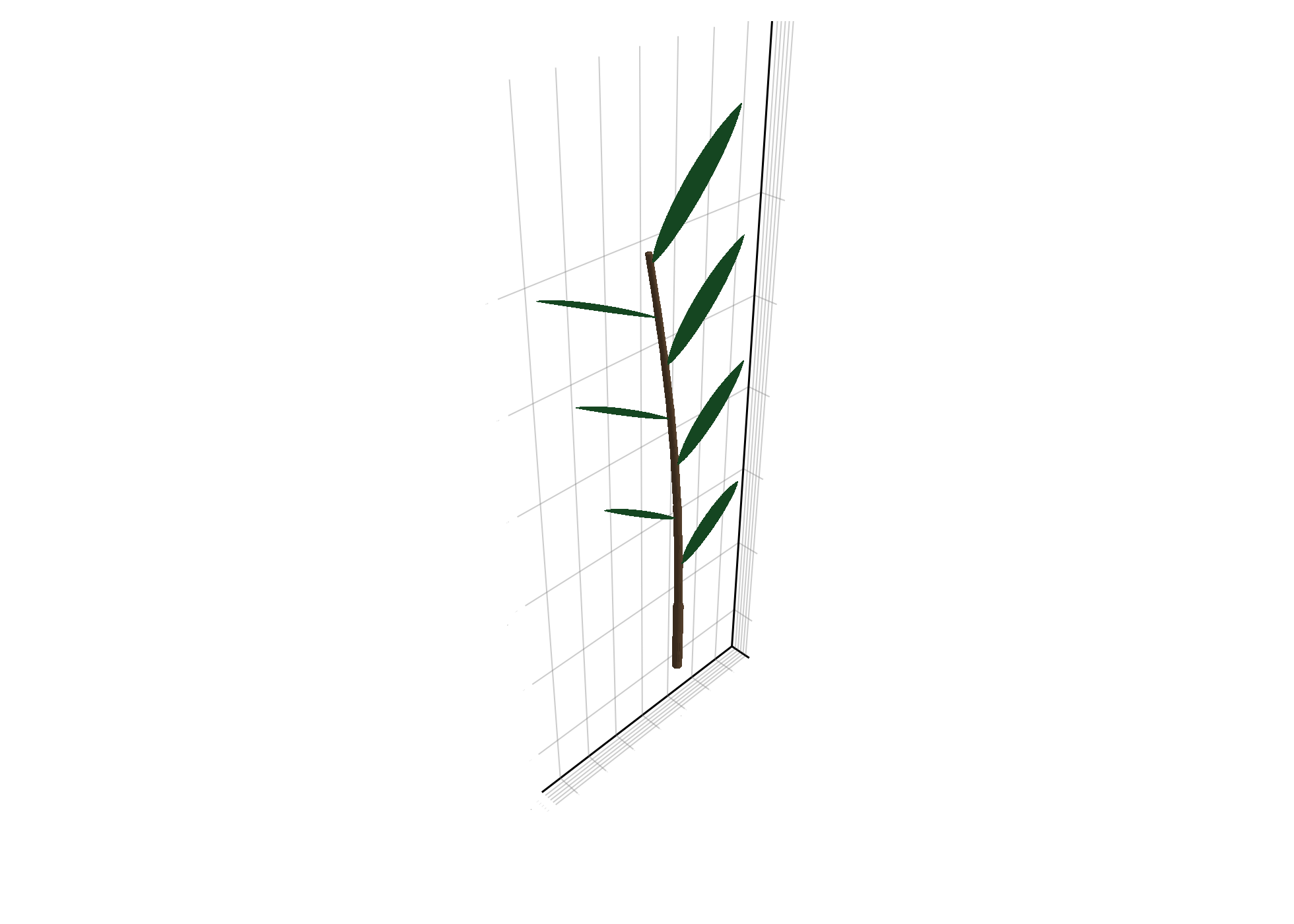
Using emit_phytomer!
If your growth logic is naturally "one internode plus one leaf", emit_phytomer! is shorter and clearer.
small_plant = Node(NodeMTG(:/, :Plant, 1, 1))

first_phy = emit_phytomer!(
    small_plant;
    internode=(link=:/, index=1, length=0.20, width=0.022),
    leaf=(index=1, offset=0.15, length=0.22, width=0.05, thickness=0.02, y_insertion_angle=52.0),
)

second_phy = emit_phytomer!(
    first_phy.internode;
    internode=(index=2, length=0.18, width=0.020),
    leaf=(index=2, offset=0.14, length=0.24, width=0.055, thickness=0.02, phyllotaxy=180.0, y_insertion_angle=54.0),
)

rebuild_geometry!(small_plant, prototypes)
plantviz(small_plant, figure=(size=(820, 560),))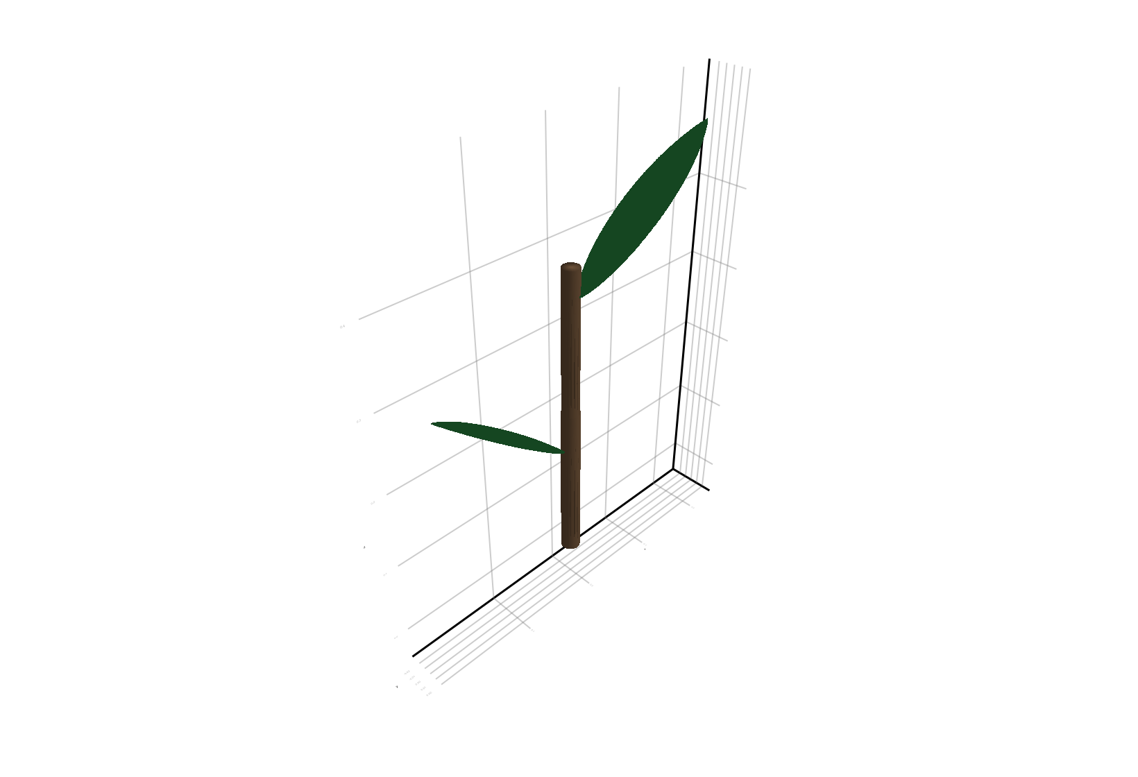
Prototype Selection and Overrides
You have two main ways to control organ shape:
1. One prototype per organ symbol
This is the simplest pattern:
prototypes = Dict(
    :Internode => internode_proto,
    :Leaf => leaf_proto,
)
Then every :Leaf uses the same prototype unless overridden.
2. Store prototype choice or shape overrides on each node
This is useful when different leaves need different shapes.
emit_leaf!(
    axis;
    prototype=:Leaf,
    prototype_overrides=(bend=0.6, tip_drop=0.15),
)
The override values are stored directly in the MTG node, so they remain explicit and inspectable.
Performance Model
The intended performance pattern is:
| Stage | Cheap or expensive? | Notes |
|---|---|---|
emit_* | cheap | only topology + attributes |
grow_* / set_growth_attributes! | cheap | attribute mutation only |
rebuild_geometry! | more expensive | traverses nodes and creates geometry |
plantviz(...) | very expensive | depends on scene size |
Recommended practice:
perform many growth/attribute updates
rebuild geometry only when needed for export, plotting, or checkpoints
keep growth logic explicit in Julia rather than hiding it inside geometry callbacks
Minimal PlantSimEngine Example
If you use PlantSimEngine, the same API is available with Status objects.
This is an optional workflow that requires PlantSimEngine to be installed and loaded.
using PlantGeom
using PlantSimEngine

# inside a PlantSimEngine model:
new_internode = emit_internode!(status.node, sim_object; length=0.03, width=0.004)
new_leaf = emit_leaf!(new_internode, sim_object; length=0.10, width=0.03, leaf_stage=:juvenile)

grow_length!(new_internode; delta=0.005)
set_growth_attributes!(new_leaf; leaf_stage=:expanding, age=1)
PlantGeom still handles topology and geometry metadata, while PlantSimEngine still owns status initialization through add_organ! (called inside emit_*).
For a complete runnable example with:
a custom PlantSimEngine growth model
a
ModelMappingmeteorological forcing
a call to
run!and a final 3D reconstruction
see Growth API with PlantSimEngine.
Copy-Paste Example
If you want one block to paste into a Julia session, this is the shortest complete example from this page:
using PlantGeom
using MultiScaleTreeGraph
using GeometryBasics
using Colors
using CairoMakie

CairoMakie.activate!()

stem_ref = RefMesh(
    "stem",
    GeometryBasics.mesh(
        GeometryBasics.Cylinder(
            Point(0.0, 0.0, 0.0),
            Point(1.0, 0.0, 0.0),
            0.5,
        ),
    ),
    RGB(0.48, 0.36, 0.25),
)

leaf_ref = lamina_refmesh(
    "leaf";
    length=1.0,
    max_width=1.0,
    material=RGB(0.19, 0.61, 0.29),
)

prototypes = Dict(
    :Internode => RefMeshPrototype(stem_ref),
    :Leaf => PointMapPrototype(
        leaf_ref;
        defaults=(base_angle_deg=42.0, bend=0.30, tip_drop=0.08),
        intrinsic_shape=params -> LaminaMidribMap(
            base_angle_deg=params.base_angle_deg,
            bend=params.bend,
            tip_drop=params.tip_drop,
        ),
    ),
)

plant = Node(NodeMTG(:/, :Plant, 1, 1))
axis = emit_internode!(plant; link=:/, index=1, length=0.18, width=0.022)

for i in 2:8
    axis = emit_internode!(axis; index=i, length=0.17 * 0.95^(i - 2), width=0.021 * 0.93^(i - 2))
    emit_leaf!(
        axis;
        index=i,
        offset=0.80 * axis[:Length],
        length=0.22 + 0.018 * i,
        width=0.032 + 0.003 * i,
        thickness=0.010 + 0.0015 * i,
        phyllotaxy=isodd(i) ? 0.0 : 180.0,
        y_insertion_angle=54.0,
        prototype=:Leaf,
        prototype_overrides=(bend=0.12 + 0.06 * i, tip_drop=0.02 * i),
    )
end

rebuild_geometry!(plant, prototypes)
plantviz(plant, figure=(size=(980, 700),))
Troubleshooting
If the plant topology exists but nothing is visible, check that you actually called
rebuild_geometry!.If leaf shape overrides do not change anything, verify the override names against the prototype parameters.
If geometry orientation looks wrong, check that your prototypes are authored with organ length along local
+Xwhen using the default AMAP convention.If plotting becomes slow, lower rebuild frequency rather than trying to optimize the growth loop first.