MTG Reconstruction Tutorial
Page Info
Audience: Beginner to Intermediate
Prerequisites: beginner reconstruction quickstart
Time: 12 minutes
Output: First automatic 3D reconstruction from MTG measurements
This page is a practical tutorial for reconstructing geometry from an MTG with attributes coming from measurements or models. It is the first step in the "reconstruct from MTG" workflow, and it is designed to be accessible to users who have completed the beginner reconstruction quickstart.
This page explains how to reconstruct a plant from an MTG that contains:
topology (
:<,:+,:/)measurements such as
Length,Width, insertion angles, Euler anglesoptionally explicit coordinates
The two reconstruction functions you will use are:
set_geometry_from_attributes!(mtg, prototypes; ...)
reconstruct_geometry_from_attributes!(mtg, prototypes; ...)
For most users, set_geometry_from_attributes! is the right starting point.
How does it work?
Each organ is represented by a "base" geometry called a prototype mesh. This prototype defines the shape of the organ in a normalized way (e.g. length = 1, width = 1). The reconstruction functions read the MTG topology and attributes, and use them to place and deform the prototype geometry on each node so the resulting mesh has the correct size and orientation. The resulting geometry is stored in node[:geometry] and can be visualized with plantviz.
What You Need in the MTG
You do not need every possible attribute to begin.
Minimum useful measurement set
The minimum set of attributes to get a useful reconstruction is:
| Column | Meaning | Why it matters |
|---|---|---|
Length | organ length | scales the organ along its main axis |
Width | organ width | scales the organ laterally |
Thickness | organ thickness | optional but useful for non-flat organs |
With just these three attributes, you can already get a recognizable plant structure. The reconstruction will be very basic, with all organs oriented in the same direction and attached at the same point on their bearer, but it's a start! It may also be largely enough for some applications, as long as the architecture of the plant is highly predictable.
Standard set for topology-based plant reconstruction
Usually, you will want to add insertion angles and Euler angles to get more realistic organ orientations. This is the standard set of attributes used in topology-based reconstruction:
| Column | Meaning |
|---|---|
Length, Width, Thickness | organ size |
XInsertionAngle, YInsertionAngle, ZInsertionAngle | orientation at attachment |
XEuler, YEuler, ZEuler | extra local rotation after insertion |
Offset | where a :+ organ is attached along its bearer |
BorderInsertionOffset | lateral shift on the bearer cross-section |
With these attributes, you can get a much more realistic reconstruction, with organs oriented in different directions and attached at different points on their bearer. This is the most common set of attributes used for reconstructing from measured MTGs.
Note
Insertion angles define how an organ is attached to its parent, so they describe the plant architecture itself. Euler angles are applied afterward as local pose refinements: they are useful for twisting, rolling, or slightly reorienting the organ mesh without changing the biological meaning of the attachment. In practice, use insertion angles for the structural reconstruction, and Euler angles only for geometric corrections or fine pose adjustments.
Optional explicit-coordinate set
Sometimes you may have explicit coordinates for node positions, such as XX, YY, ZZ for the start of the node, and EndX, EndY, EndZ for the end of the node. If you have these, you can use them to reconstruct geometry with more direct control over node placement. However, you will need to choose an explicit coordinate mode in AmapReconstructionOptions to tell PlantGeom how to interpret these coordinates. This is typically what is used when reconstructing from an MTG that was measured with a 3D digitizer or that was exported from e.g. plantscan3d.
| Column | Meaning |
|---|---|
XX, YY, ZZ | explicit node start position |
EndX, EndY, EndZ | explicit node end position |
If you measure explicit coordinates, read Explicit Coordinates: Which Option Should I Use? after this tutorial.
To run this tutorial, you need to install and import the following packages:
using PlantGeom
using MultiScaleTreeGraph
using Colors
using CairoMakie
using GeometryBasics
1. Load the MTG
The example file used here is test/files/reconstruction_standard.mtg.
mtg_file = joinpath(pkgdir(PlantGeom), "test", "files", "reconstruction_standard.mtg")
mtg = read_mtg(mtg_file)
Symbols: Plant Internode Leaf
Scales: 1 2 2
/ 1: Plant
└─ / 2: Internode
├─ + 3: Leaf
└─ < 4: Internode
├─ + 5: Leaf
└─ < 6: Internode
├─ + 7: Leaf
└─ < 8: Internode
└─ + 9: LeafThe MTG file is as follows:
CODE:	FORM-A

CLASSES:
SYMBOL	SCALE	DECOMPOSITION	INDEXATION	DEFINITION
Plant	1	FREE	FREE	IMPLICIT
Internode	2	FREE	FREE	IMPLICIT
Leaf	2	FREE	FREE	IMPLICIT

DESCRIPTION:
LEFT	RIGHT	RELTYPE	MAX

FEATURES:
NAME	TYPE
Thickness	REAL
Length	REAL
Width	REAL
YEuler	REAL
XEuler	REAL
XInsertionAngle	REAL
YInsertionAngle	REAL
Offset	REAL
BorderInsertionOffset	REAL

MTG:
ENTITY-CODE		Thickness	Length	Width	YEuler	XEuler	XInsertionAngle	YInsertionAngle	Offset	BorderInsertionOffset
/Plant1
^/Internode1		0.035	0.28	0.035	1.438276615812609
	+Leaf1	0.002	0.235	0.116		-18.0	45.0	53.68294196961579	0.2296	0.0175
^<Internode2		0.03325	0.2632	0.03325	2.5244129544236893
	+Leaf2	0.002	0.25	0.122		-18.0	135.0	53.81859485365136	0.215824	0.016625
^<Internode3		0.031587500000000004	0.24740800000000002	0.031587500000000004	2.9924849598121632
	+Leaf3	0.002	0.265	0.128		-18.0	225.0	52.28224001611974	0.20287456	0.015793750000000002
^<Internode4		0.030008125	0.23256352	0.030008125	2.727892280477045
^+Leaf4		0.002	0.28	0.134		-18.0	315.0	50.48639500938415	0.1907020864	0.0150040625
2. Define Organ Prototypes
First, we need to define the prototype meshes for the organs we want to reconstruct. In this example, we have two organ types: Internode and Leaf. We will create a simple cylindrical mesh for the internode and a flat mesh for the leaf.
These prototypes are unit-sized (length=1, width=1). MTG columns such as Length and Width will scale them during reconstruction.
internode_refmesh = RefMesh(
    "Stem",
    GeometryBasics.mesh(
        GeometryBasics.Cylinder(
            Point(0.0, 0.0, 0.0),
            Point(1.0, 0.0, 0.0),
            0.5,
        ),
    ),
    RGB(0.55, 0.45, 0.35),
)

leaf_refmesh = RefMesh(
    "Leaf",
    GeometryBasics.Mesh(
        [
            Point(0.0, -0.05, 0.0),
            Point(0.0, 0.05, 0.0),
            Point(0.2, 0.0, 0.0),
            Point(1.2, 0.0, 0.0),
            Point(0.7, -0.45, 0.0),
            Point(0.7, 0.45, 0.0),
        ],
        [
            TriangleFace(1, 2, 3),
            TriangleFace(3, 5, 4),
            TriangleFace(3, 6, 4),
        ],
    ),
    RGB(0.10, 0.50, 0.20),
)

prototypes = Dict(
    :Internode => RefMeshPrototype(internode_refmesh),
    :Leaf => RefMeshPrototype(leaf_refmesh),
)
Dict{Symbol, RefMeshPrototype{RefMesh{String, GeometryBasics.Mesh{3, Float64, GeometryBasics.TriangleFace{Int64}, (:position,), Tuple{Vector{Point{3, Float64}}}, Vector{GeometryBasics.TriangleFace{Int64}}}, ColorTypes.RGB{Float64}, Vector{Vec{3, Float64}}, Nothing}}} with 2 entries:
:Leaf => RefMeshPrototype{RefMesh{String, Mesh{3, Float64, TriangleFace{…
:Internode => RefMeshPrototype{RefMesh{String, Mesh{3, Float64, TriangleFace{…3. Reconstruct Geometry
Now we simply call set_geometry_from_attributes!. It will read the MTG topology and attributes, and use them to scale, rotate and translate the prototype geometry on each node so the resulting mesh has the correct size and orientation. The resulting geometry is stored in node[:geometry] for each node. The attributes are interpreted according to the default_amap_geometry_convention(), which is designed to work with standard MTGs measured in the field or exported from common plant modeling software. You can also define a custom convention if your column names or meanings differ.
set_geometry_from_attributes!(
    mtg,
    prototypes;
    convention=default_amap_geometry_convention(),
)

plantviz(mtg, color=Dict("Stem" => :tan4, "Leaf" => :forestgreen))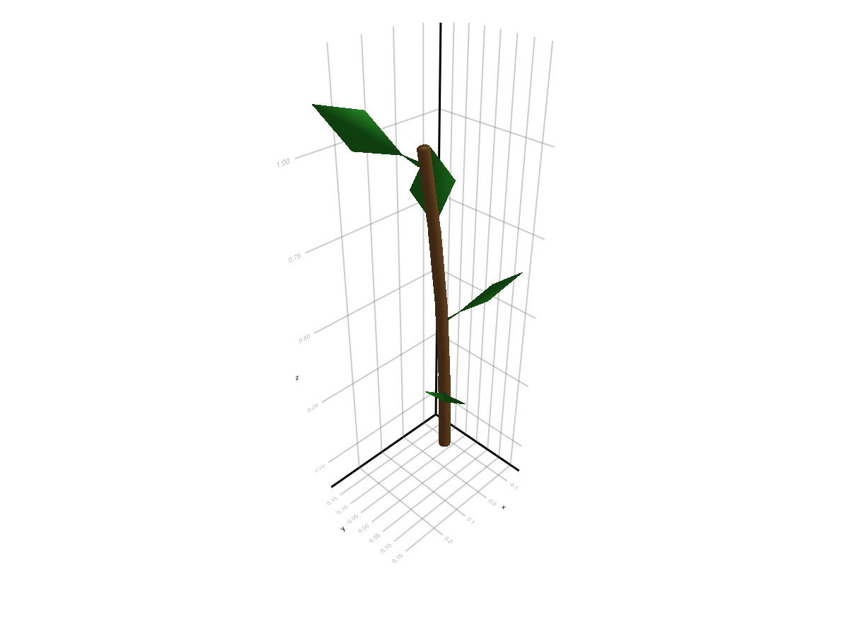
And that's it!
4. Change One Reconstruction Option
You can customize the default behavior using AmapReconstructionOptions and and pass it as an argument to set_geometry_from_attributes!:
set_geometry_from_attributes!(...; amap_options=opts)For example, you can choose to override the default insertion angles for second-order organs (e.g. leaves) to make them more erect by overriding their Y insertion angle:
mtg_default = read_mtg(mtg_file)
mtg_custom = read_mtg(mtg_file)

set_geometry_from_attributes!(
    mtg_default,
    prototypes;
    convention=default_amap_geometry_convention(),
)

opts = AmapReconstructionOptions(
    order_override_mode=:override,
    insertion_y_by_order=Dict(2 => 25.0),
)

set_geometry_from_attributes!(
    mtg_custom,
    prototypes;
    convention=default_amap_geometry_convention(),
    amap_options=opts,
)f = Figure(size=(980, 420))
ax1 = Axis3(f[1, 1], title="Default", aspect=:data)
plantviz!(ax1, mtg_default, color=Dict("Stem" => :tan4, "Leaf" => :forestgreen))
ax2 = Axis3(f[1, 2], title="Custom option", aspect=:data)
plantviz!(ax2, mtg_custom, color=Dict("Stem" => :tan4, "Leaf" => :darkgreen))
f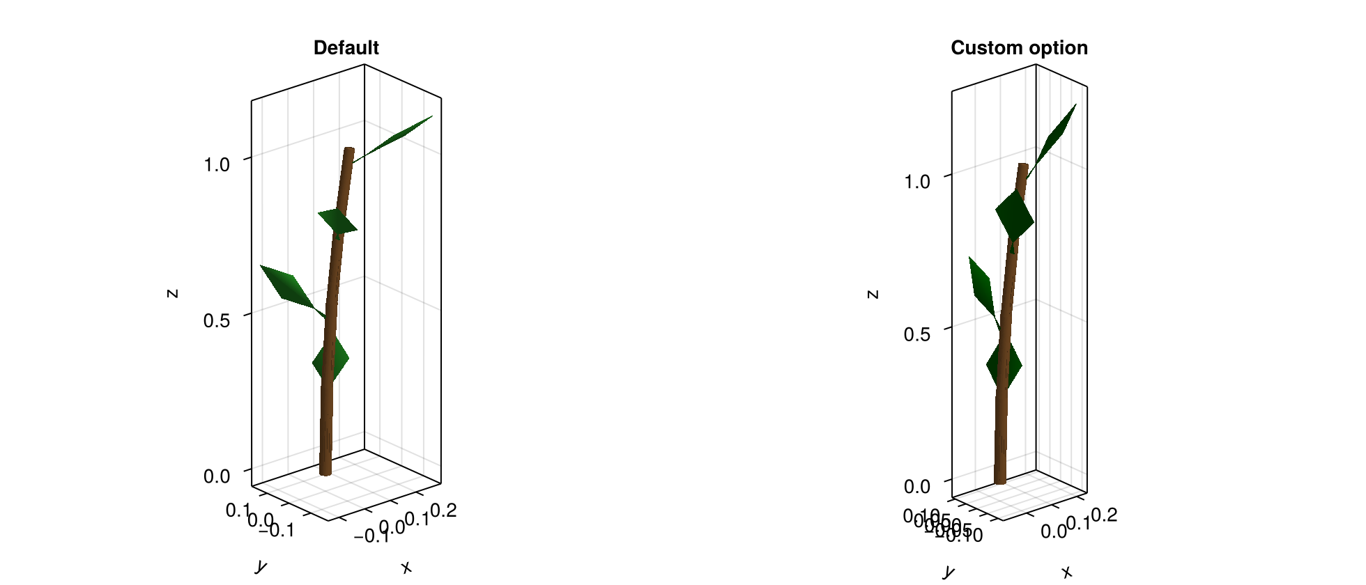
You can read the full list of options you can modify using the documentation of the function directly:
?AmapReconstructionOptionsOr head onto the next page.
What To Measure First
If you are building your own measurement workflow, a good order is:
Length,Width,ThicknessOffsetinsertion angles (
XInsertionAngle,YInsertionAngle,ZInsertionAngle)Euler corrections only if needed
explicit coordinates only if your data source already provides them
This gives a useful reconstruction without measuring every advanced AMAP variable.
Where To Go Next
To decide which explicit coordinate mode to use: Explicit Coordinates: Which Option Should I Use?
To see the full list of MTG columns you can define: AMAP Conventions Reference
Troubleshooting
If nothing appears, check that your MTG contains at least
LengthandWidthon the organs you want to reconstruct.If the organ orientation looks wrong, first verify that your prototype meshes are authored with length along local
+X.If your column names differ from the defaults, define a custom
GeometryConvention.