Procedural / Extrusion Geometry
Page Info
Audience: Intermediate to Advanced
Prerequisites: comfortable with
RefMeshbasics and transformsTime: 20 minutes
Output: Parametric/extruded organ geometry and low-level control (Level 3 concept page)
PlantGeom supports two complementary geometry workflows:
shared geometry with
RefMesh+Geometry(ref_mesh=..., transformation=...)shared geometry with per-node shape deformation via
PointMappedGeometryper-node procedural geometry with
ExtrudedTubeGeometryand extrusion helpers
If you already know the RefMesh workflow, this page is the extrusion counterpart.
When to Use Which Workflow
Use RefMesh + Geometry when:
many nodes share the same base organ mesh
only node transform differs (scale/rotation/translation)
you want the classic OPF-style "instantiate once, transform many" pattern
Use PointMappedGeometry when:
many nodes share the same base organ topology, but each organ bends differently
you want to keep a reusable
RefMeshwhile warping it with a concrete point maporgan shape is easier to describe from a midrib/guide curve than from rigid transforms alone
Use procedural extrusion when:
each axis/organ needs its own path or profile
geometry is easier to define from centerlines and section evolution
you want to build geometry directly from node parameters
Point-Mapped Geometry
PointMappedGeometry fills the gap between rigid instancing (Geometry) and fully procedural mesh generation (ExtrudedTubeGeometry): the base organ mesh is still reusable, but each node can carry its own deformation map.
PlantGeom now includes a small midrib-driven lamina toolkit for that workflow:
RationalBezierCurve: NURBS-like weighted Bezier midriblamina_midrib: convenience weighted curve builderLaminaMidribMap: point map that wraps a flat lamina around a midribLaminaTwistRollMap: local lamina torsion and edge-roll mapLaminaAnticlasticWaveMap: anticlastic margin map (one side up, the other down)BiomechanicalBendingTransform: cantilever-style organ bending from Young's moduluscompose_point_maps: compose multiple point maps into onelamina_mesh/lamina_refmesh: reusable flat blade reference mesh
For these cereal point maps, parameters are normalized for a unit blade frame (x ∈ [0, 1], |y| ≤ 0.5). Use lamina_refmesh(...; max_width=1.0) and apply physical width later via node transforms or reconstruction attributes. Note: scaling local z strongly also scales down bend amplitude, because midrib deflection is represented in local z by the point map. To define dimensions before deformation, use with_point_map_frame(...). When used through PointMappedGeometry, the input RefMesh coordinates are normalized to blade space automatically (x → [0,1], centered y) before the point-map pipeline, so framed mappings remain stable across source mesh units.
For cereal-like anticlastic ripples (opposite side displacement), use LaminaAnticlasticWaveMap with:
lateral_strength=0.0vertical_strength=1.0
This creates opposite-sign side displacement in the normal direction (+Y and -Y move in opposite Z directions), not a side-to-side zig-zag outline.
Biomechanical Cantilever Bending
For organs that should bend under gravity without explicit biomass simulation, PlantGeom provides:
final_angle: maximal beam deflection angle (from vertical, radians)local_flexion: local incremental bending contributioncalculate_segment_angles: angle profile along segment boundariesBiomechanicalBendingTransform: fast sampled non-linear transform to apply on meshes
BiomechanicalBendingTransform precomputes centerline/frame samples once, so per-vertex evaluation is interpolation only. You can apply it directly to Geometry nodes with transform_mesh! (or compose it with other transforms).
segments = collect(range(0.0, 1.0; length=8))
angles = calculate_segment_angles(25.0, deg2rad(30.0), 1.0, 0.55, segments)

bend = BiomechanicalBendingTransform(
    25.0,
    deg2rad(30.0),
    1.0,
    0.55;
    x_min=0.0,
    x_max=1.0,
    n_samples=96,
)

(angles[1], angles[end], bend(Point(1.0, 0.0, 0.0)))
(0.5235987755982988, 3.1365276012323497, [0.0175334011851262, 0.0, -0.9902165353601948])beam_length should use the same unit as your mesh local x axis (unless you explicitly adjust x_min/x_max). By default, the helper equations use length_scale=100.0 to match legacy centimeter-based formulations.
For segmented organs modeled as consecutive MTG nodes (legacy leaflet style), you can write angles directly on each segment node with update_segment_angles!.
function segmented_polyline(segment_positions, angle_deg_values)
    boundaries = vcat(segment_positions, 1.0)
    pts = Point2f[(0.0, 0.0)]
    for i in eachindex(angle_deg_values)
        θ = deg2rad(angle_deg_values[i])
        ds = boundaries[i + 1] - boundaries[i]
        x_prev = pts[end][1]
        z_prev = pts[end][2]
        push!(pts, Point2f(x_prev + ds * sin(θ), z_prev + ds * cos(θ)))
    end
    pts
end

mtg = Node(NodeMTG(:/, :Plant, 1, 1))
leaflet_soft = Node(mtg, NodeMTG(:+, :Leaflet, 1, 2))
leaflet_stiff = Node(mtg, NodeMTG(:+, :Leaflet, 2, 2))
segment_positions = [0.0, 0.20, 0.42, 0.66, 0.88]

for (i, pos) in enumerate(segment_positions)
    s_soft = Node(leaflet_soft, NodeMTG(:/, :LeafletSegment, i, 3))
    s_stiff = Node(leaflet_stiff, NodeMTG(:/, :LeafletSegment, i, 3))
    s_soft[:segment_boundaries] = pos
    s_stiff[:segment_boundaries] = pos
end

update_segment_angles!(
    leaflet_soft,
    18.0,
    deg2rad(26.0),
    1.0,
    0.55;
    segment_symbol=:LeafletSegment,
    position_key=:segment_boundaries,
    angle_key=:zenithal_angle,
    degrees=true,
)
update_segment_angles!(
    leaflet_stiff,
    220.0,
    deg2rad(26.0),
    1.0,
    0.55;
    segment_symbol=:LeafletSegment,
    position_key=:segment_boundaries,
    angle_key=:zenithal_angle,
    degrees=true,
)

soft_segments = descendants(leaflet_soft, symbol=:LeafletSegment)
stiff_segments = descendants(leaflet_stiff, symbol=:LeafletSegment)
angles_soft = [s[:zenithal_angle] for s in soft_segments]
angles_stiff = [s[:zenithal_angle] for s in stiff_segments]

soft_poly = segmented_polyline(segment_positions, angles_soft)
stiff_poly = segmented_polyline(segment_positions, angles_stiff)

fig = Figure(size=(780, 320))
ax = Axis(fig[1, 1], xlabel="Projected x", ylabel="Projected z", title="Segment-chain bending (soft vs stiff)")
lines!(ax, soft_poly, color=RGBA(0.14, 0.53, 0.26, 0.95), linewidth=4, label="soft (low Young)")
scatter!(ax, soft_poly, color=RGBA(0.14, 0.53, 0.26, 0.95), markersize=8)
lines!(ax, stiff_poly, color=RGBA(0.16, 0.36, 0.70, 0.95), linewidth=4, label="stiff (high Young)")
scatter!(ax, stiff_poly, color=RGBA(0.16, 0.36, 0.70, 0.95), markersize=8)
axislegend(ax, position=:rb)
fig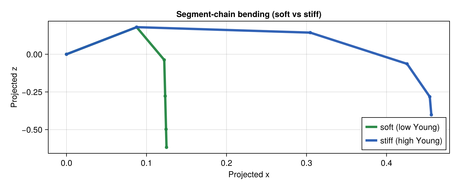
leaf_ref = lamina_refmesh(
    "CerealBlade";
    length=1.0,
    max_width=1.0,
    n_long=28,
    n_half=4,
    material=RGB(0.22, 0.62, 0.24),
)

base_leaf = PointMappedGeometry(
    leaf_ref,
    with_point_map_frame(compose_point_maps(
        LaminaTwistRollMap(tip_twist_deg=3.0, roll_strength=0.05),
        LaminaMidribMap(base_angle_deg=46.0, bend=0.02, tip_drop=0.00),
    ); length=1.0, width=0.12, z_scale=1.0),
)
steeper_leaf = PointMappedGeometry(
    leaf_ref,
    with_point_map_frame(compose_point_maps(
        LaminaTwistRollMap(
            tip_twist_deg=26.0,
            roll_strength=0.32,
            roll_exponent=1.2,
        ),
        LaminaMidribMap(base_angle_deg=22.0, bend=1.0, tip_drop=1.0),
    ); length=1.0, width=0.12, z_scale=1.0);
    transformation=PlantGeom.compose(
        PlantGeom.Translation(0.0, 0.22, 0.0),
    ),
)

fig = Figure(size=(920, 360))
ax = Axis3(fig[1, 1], title="PointMappedGeometry: cereal leaf angle + bend", aspect = :data)
mesh!(ax, PlantGeom.geometry_to_mesh(base_leaf), color=RGBA(0.30, 0.70, 0.28, 0.95))
mesh!(ax, PlantGeom.geometry_to_mesh(steeper_leaf), color=RGBA(0.12, 0.50, 0.18, 0.95))
fig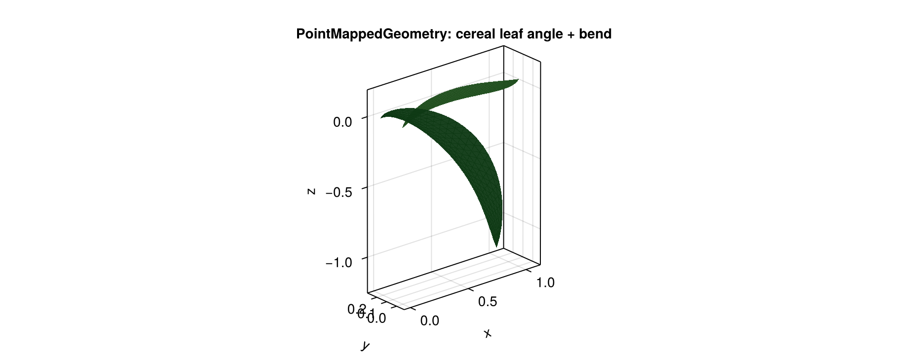
The same pattern scales to a small cereal plant:
mtg = Node(NodeMTG(:/, :Plant, 1, 1))
stem = Node(mtg, NodeMTG(:/, :Stem, 1, 2))
stem_path = [
    Point(0.0, 0.0, 0.0),
    Point(0.0, 0.0, 0.44),
    Point(0.0, 0.0, 0.92),
    Point(0.0, 0.0, 1.26),
]
stem[:geometry] = ExtrudedTubeGeometry(
    stem_path;
    n_sides=14,
    radius=0.022,
    radii=[1.0, 0.90, 0.74, 0.50],
    torsion=false,
    cap_ends=true,
    material=RGB(0.54, 0.76, 0.38),
)

blade_ref = lamina_refmesh(
    "CerealBlade";
    length=1.0,
    max_width=1.0,
    n_long=40,
    n_half=8,
    material=RGB(0.20, 0.60, 0.22),
)

leaf_specs = [
    (z=0.20, azimuth_deg=-35.0, insertion_tilt_deg=42.0, base_angle_deg=34.0, bend=0.16, tip_drop=0.04, twist=8.0, roll=0.18, wave_amp=0.008, wave_len=0.23, scale=0.82),
    (z=0.56, azimuth_deg=84.0, insertion_tilt_deg=48.0, base_angle_deg=44.0, bend=0.30, tip_drop=0.08, twist=18.0, roll=0.30, wave_amp=0.010, wave_len=0.19, scale=0.96),
    (z=0.90, azimuth_deg=208.0, insertion_tilt_deg=54.0, base_angle_deg=54.0, bend=0.46, tip_drop=0.14, twist=34.0, roll=0.44, wave_amp=0.012, wave_len=0.15, scale=1.05),
]

for (i, spec) in enumerate(leaf_specs)
    leaf = Node(stem, NodeMTG(:+, :Leaf, i, 2))
    point_map = compose_point_maps(
        LaminaAnticlasticWaveMap(
            amplitude=spec.wave_amp / 0.12,
            wavelength=spec.wave_len,
            edge_exponent=1.6,
            progression_exponent=1.1,
            base_damping=5.0,
            phase_deg=25.0 * i,
            asymmetry=0.10,
            lateral_strength=0.0,
            vertical_strength=1.0,
        ),
        LaminaTwistRollMap(
            tip_twist_deg=spec.twist,
            roll_strength=spec.roll,
            roll_exponent=1.2,
        ),
        LaminaMidribMap(
            base_angle_deg=spec.base_angle_deg,
            bend=spec.bend,
            tip_drop=spec.tip_drop,
        ),
    )
    leaf[:geometry] = PointMappedGeometry(
        blade_ref,
        with_point_map_frame(
            point_map;
            length=spec.scale,
            width=0.12 * spec.scale,
            z_scale=spec.scale,
        );
        transformation=PlantGeom.compose(
            PlantGeom.Translation(0.0, 0.0, spec.z),
            PlantGeom.LinearMap(PlantGeom.RotZ(deg2rad(spec.azimuth_deg))),
            PlantGeom.LinearMap(PlantGeom.RotMatrix(PlantGeom.AngleAxis(deg2rad(-spec.insertion_tilt_deg), 0.0, 1.0, 0.0))),
        ),
    )
end

terminal_leaf = Node(stem, NodeMTG(:+, :Leaf, length(leaf_specs) + 1, 2))
stem_top_z = stem_path[end][3]
terminal_leaf[:geometry] = PointMappedGeometry(
    blade_ref,
    with_point_map_frame(compose_point_maps(
        LaminaAnticlasticWaveMap(
            amplitude=0.008 / 0.12,
            wavelength=0.20,
            edge_exponent=1.6,
            progression_exponent=1.1,
            base_damping=5.0,
            phase_deg=10.0,
            asymmetry=0.05,
            lateral_strength=0.0,
            vertical_strength=1.0,
        ),
        LaminaTwistRollMap(
            tip_twist_deg=10.0,
            roll_strength=0.20,
            roll_exponent=1.1,
        ),
        LaminaMidribMap(
            base_angle_deg=62.0,
            bend=0.22,
            tip_drop=0.05,
        ),
    ); length=0.76, width=0.12 * 0.76, z_scale=0.76);
    transformation=PlantGeom.compose(
        PlantGeom.Translation(0.0, 0.0, stem_top_z),
        PlantGeom.LinearMap(PlantGeom.RotZ(deg2rad(6.0))),
        PlantGeom.LinearMap(PlantGeom.RotMatrix(PlantGeom.AngleAxis(deg2rad(-48.0), 0.0, 1.0, 0.0))),
    ),
)

plantviz(mtg, color=Dict("CerealBlade" => RGB(0.20, 0.60, 0.22), "ExtrudedTube" => RGB(0.54, 0.76, 0.38)))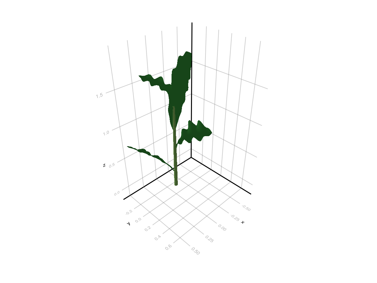
Cereal Anticlastic Wave (Normal Direction)
This focused comparison isolates the anticlastic effect only: same base blade and bending, with or without LaminaAnticlasticWaveMap.
compare_ref = lamina_refmesh(
    "CerealBladeCompare";
    length=1.0,
    max_width=1.0,
    n_long=72,
    n_half=14,
    material=RGB(0.20, 0.60, 0.22),
)

smooth_leaf = PointMappedGeometry(
    compare_ref,
    compose_point_maps(
        LaminaTwistRollMap(tip_twist_deg=20.0, roll_strength=0.32, roll_exponent=1.15),
        LaminaMidribMap(base_angle_deg=34.0, bend=0.56, tip_drop=0.16),
    );
    transformation=PlantGeom.compose(
        PlantGeom.Translation(0.0, -0.20, 0.0),
        PlantGeom.LinearMap(Diagonal([1.0, 0.14, 0.14])),
    ),
)

wavy_leaf = PointMappedGeometry(
    compare_ref,
    compose_point_maps(
        LaminaAnticlasticWaveMap(
            amplitude=0.022 / 0.14,
            wavelength=0.145,
            edge_exponent=1.7,
            progression_exponent=1.1,
            base_damping=4.5,
            phase_deg=18.0,
            lateral_strength=0.0,
            vertical_strength=1.0,
        ),
        LaminaTwistRollMap(tip_twist_deg=20.0, roll_strength=0.32, roll_exponent=1.15),
        LaminaMidribMap(base_angle_deg=34.0, bend=0.56, tip_drop=0.16),
    );
    transformation=PlantGeom.compose(
        PlantGeom.Translation(0.0, 0.20, 0.0),
        PlantGeom.LinearMap(Diagonal([1.0, 0.14, 0.14])),
    ),
)

fig = Figure(size=(1200, 520))
ax = Axis3(
    fig[1, 1];
    title="Cereal leaf anticlastic wave (top: wavy, bottom: smooth)",
    azimuth=1.45,
    elevation=0.36,
    perspectiveness=0.7,
)
mesh!(ax, PlantGeom.geometry_to_mesh(smooth_leaf), color=RGBA(0.18, 0.58, 0.22, 0.95))
mesh!(ax, PlantGeom.geometry_to_mesh(wavy_leaf), color=RGBA(0.14, 0.50, 0.18, 0.95))
Makie.xlims!(ax, -0.03, 1.05)
Makie.ylims!(ax, -0.33, 0.33)
Makie.zlims!(ax, -0.26, 0.56)
fig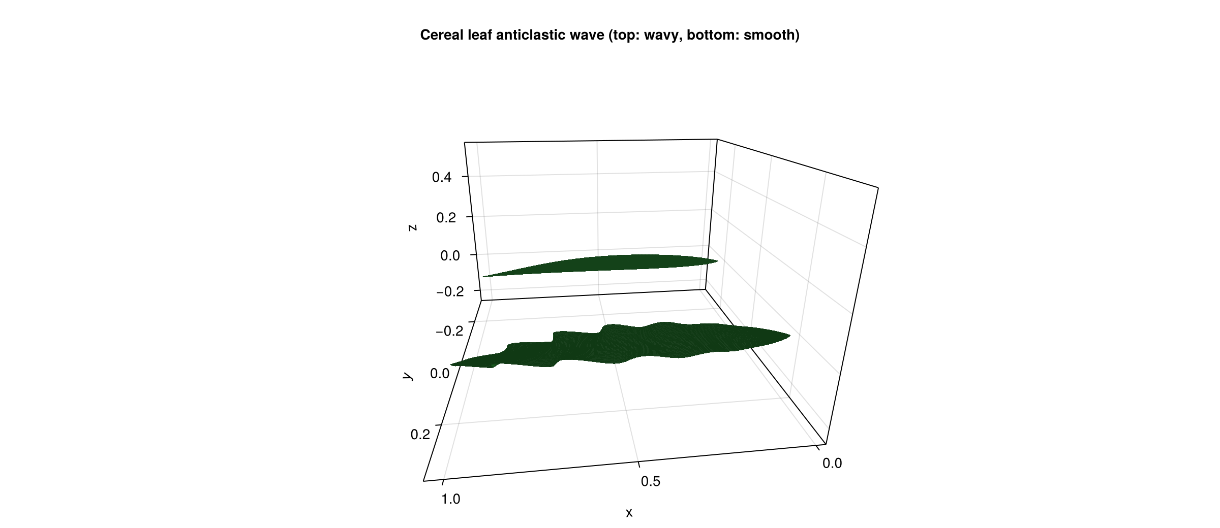
This deforms the blade itself. If you instead want topology-driven component bending across segmented organs, use the AMAP stiffness/orthotropy pipeline from Conventions Reference.
Node-Level Procedural Geometry
ExtrudedTubeGeometry is a procedural node geometry source. It does not point to an existing RefMesh; the local mesh is generated from path/section parameters.
using PlantGeom
using MultiScaleTreeGraph
using Colors
using GeometryBasics

mtg = Node(NodeMTG(:/, :Plant, 1, 1))
axis = Node(mtg, NodeMTG(:/, :Internode, 1, 2))

axis[:geometry] = ExtrudedTubeGeometry(
    [
        Point(0.0, 0.0, 0.0),
        Point(0.3, 0.02, 0.01),
        Point(0.7, 0.07, 0.04),
        Point(1.1, 0.12, 0.06),
    ];
    n_sides=16,
    radius=0.045,
    radii=[1.0, 0.9, 0.75, 0.6],  # taper
    torsion=false,
    cap_ends=true,
    material=RGB(0.45, 0.35, 0.25),
    transformation=PlantGeom.Translation(0.2, 0.0, 0.0),
)
Main parameters:
path: centerline pointsn_sides,radius: base circular sectionradii: isotropic scaling along the pathwidths,heights: anisotropic scaling (overrideradiiwhen provided)path_normals,torsion: local frame controlcap_ends: optional end caps for closed circular sectionstransformation: post-extrusion transform
Reusable Extrusion as RefMesh
If many nodes share the same procedural shape, generate it once and wrap it in a RefMesh, then keep using classic Geometry.
leaf_section = leaflet_midrib_profile(; lamina_angle_deg=42.0, scale=0.5)
leaf_path = [Point(0.0, 0.0, 0.0), Point(0.5, 0.0, 0.08), Point(1.0, 0.0, 0.12)]

leaf_ref = extrude_profile_refmesh(
    "leaf_extruded",
    leaf_section,
    leaf_path;
    widths=[1.0, 0.8, 0.5],
    heights=[1.0, 0.9, 0.7],
    torsion=true,
    close_section=false,
    cap_ends=false,
    material=RGB(0.15, 0.55, 0.25),
)
You can also build mesh first (extrude_profile_mesh, extrude_tube_mesh) then manually wrap it with RefMesh(...).
Path, Profile, and Lathe Helpers
The helpers below cover the full workflow:
section/profile builders
path interpolation
scalar interpolation
lathe mesh generation
1) Profile helpers
circle_section_profile(n_sides; radius, close_loop=true): circular section points.leaflet_midrib_profile(; lamina_angle_deg, scale): open V-shaped leaflet section.
circle = circle_section_profile(14; radius=0.45, close_loop=true)
leaflet = leaflet_midrib_profile(; lamina_angle_deg=44.0, scale=0.45)

fig = Figure(size=(820, 320))
ax1 = Axis(fig[1, 1], title="circle_section_profile", aspect=DataAspect())
lines!(ax1, [p[1] for p in circle], [p[2] for p in circle], color=:steelblue, linewidth=3)
scatter!(ax1, [p[1] for p in circle], [p[2] for p in circle], color=:steelblue, markersize=7)

ax2 = Axis(fig[1, 2], title="leaflet_midrib_profile", aspect=DataAspect())
lines!(ax2, [p[1] for p in leaflet], [p[2] for p in leaflet], color=:forestgreen, linewidth=3)
scatter!(ax2, [p[1] for p in leaflet], [p[2] for p in leaflet], color=:forestgreen, markersize=9)

fig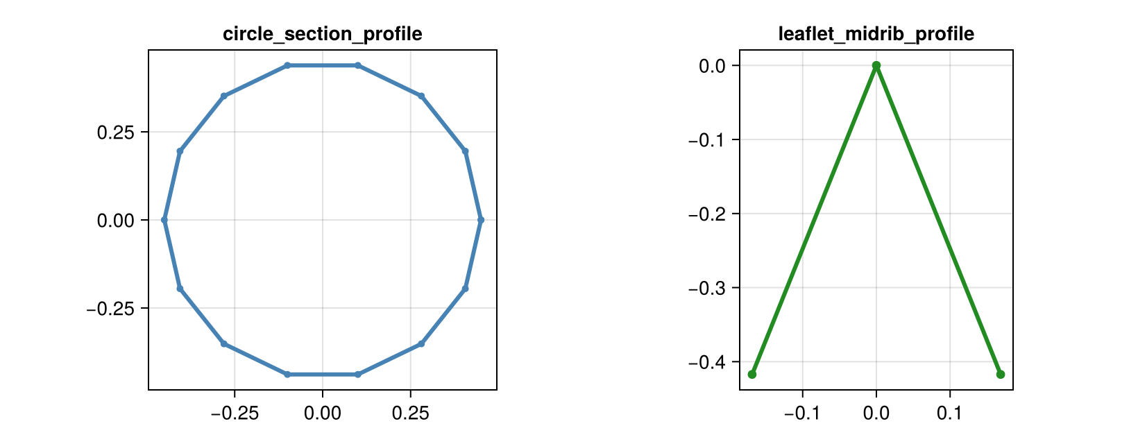
2) Path interpolation helpers
extrusion_make_path(n, key_points; key_tangents=nothing): Hermite-style interpolation.extrusion_make_spline(n, key_points): Catmull-Rom spline interpolation.
key_points = [
    Point(0.0, 0.0, 0.0),
    Point(0.2, 0.1, 0.04),
    Point(0.6, 0.14, 0.10),
    Point(1.0, 0.0, 0.16),
]

path_hermite = extrusion_make_path(70, key_points)
path_spline = extrusion_make_spline(70, key_points)

fig = Figure(size=(860, 420))
ax = Axis3(fig[1, 1], title="Path helper comparison")
lines!(
    ax,
    [p[1] for p in path_hermite],
    [p[2] for p in path_hermite],
    [p[3] for p in path_hermite],
    color=:dodgerblue,
    linewidth=3,
    label="extrusion_make_path",
)
lines!(
    ax,
    [p[1] for p in path_spline],
    [p[2] for p in path_spline],
    [p[3] for p in path_spline],
    color=:tomato,
    linewidth=3,
    label="extrusion_make_spline",
)
scatter!(
    ax,
    [p[1] for p in key_points],
    [p[2] for p in key_points],
    [p[3] for p in key_points],
    color=:black,
    markersize=12,
    label="key points",
)
axislegend(ax, position=:rb)
fig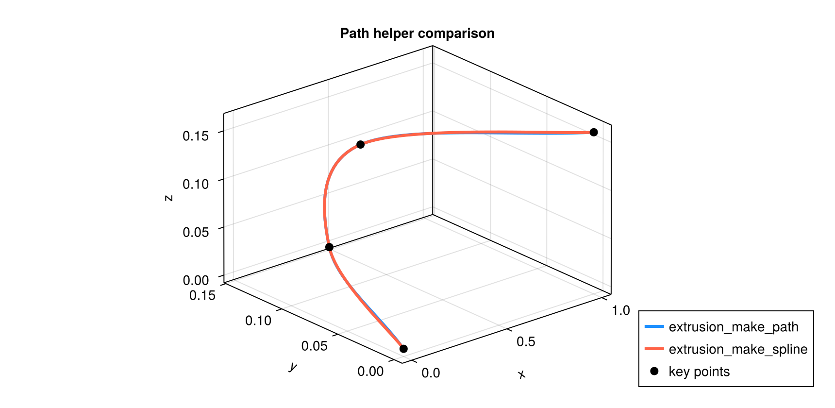
3) Scalar interpolation helpers
extrusion_make_interpolation(n, key_values): linear interpolation of key scalar values.extrusion_make_curve(z_keys, r_keys, n): AMAP-like extrema-preserving curve sampling.
key_values = [1.0, 0.92, 0.70, 0.42]
interp = extrusion_make_interpolation(60, key_values)
x_interp = range(0.0, 1.0; length=length(interp))

z_keys = [0.0, 0.22, 0.58, 1.0]
r_keys = [0.35, 0.24, 0.29, 0.10]
z_samples, r_samples = extrusion_make_curve(z_keys, r_keys, 120)

fig = Figure(size=(860, 360))
ax1 = Axis(fig[1, 1], title="extrusion_make_interpolation")
lines!(ax1, x_interp, interp, color=:purple4, linewidth=3)
scatter!(ax1, range(0.0, 1.0; length=length(key_values)), key_values, color=:black, markersize=8)

ax2 = Axis(fig[1, 2], title="extrusion_make_curve")
lines!(ax2, z_samples, r_samples, color=:darkorange3, linewidth=3)
scatter!(ax2, z_keys, r_keys, color=:black, markersize=8)

fig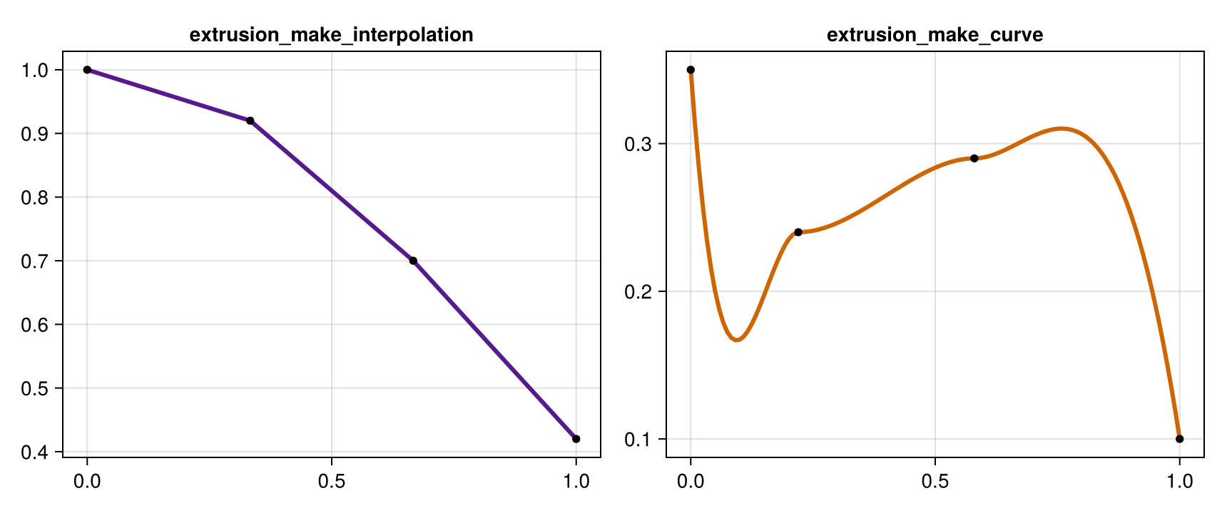
4) Visual extrusion from profile + path
You can combine helper outputs directly with extrude_profile_mesh.
section = leaflet_midrib_profile(; lamina_angle_deg=40.0, scale=0.35)
path = extrusion_make_spline(70, key_points)
widths = extrusion_make_interpolation(70, [1.0, 0.95, 0.7, 0.45])
heights = extrusion_make_interpolation(70, [1.0, 1.0, 0.85, 0.60])

mesh_leaflet = extrude_profile_mesh(
    section,
    path;
    widths=widths,
    heights=heights,
    torsion=true,
    close_section=false,
    cap_ends=false,
)

fig = Figure(size=(860, 420))
ax = Axis3(fig[1, 1], title="extrude_profile_mesh (leaflet-like)")
mesh!(ax, mesh_leaflet, color=RGBA(0.18, 0.58, 0.28, 0.95))
lines!(
    ax,
    [p[1] for p in path],
    [p[2] for p in path],
    [p[3] for p in path],
    color=:black,
    linewidth=2,
)
fig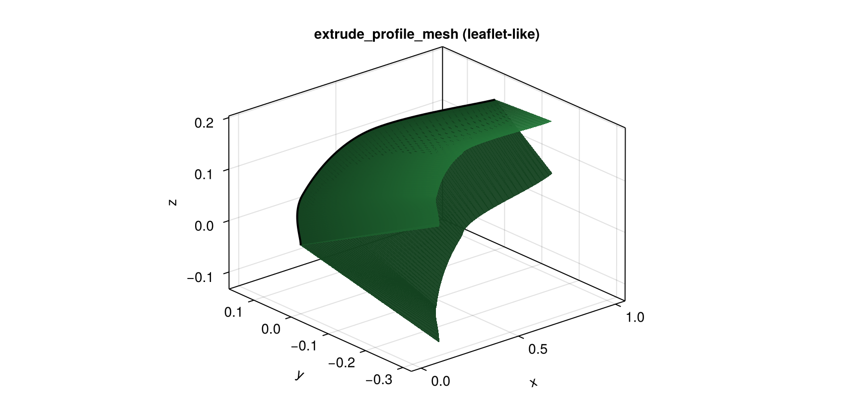
5) Lathe helpers
There are two ways to build lathe geometry:
lathe_mesh/lathe_refmesh: start from sparse key profile data.lathe_gen_mesh/lathe_gen_refmesh: start from already sampled(z, radius)arrays.
lathe_mesh(...; method=:curve) uses extrusion_make_curve (extrema-preserving), while method=:spline and method=:path use spline/Hermite interpolation.
z_keys_lathe = [0.0, 0.22, 0.58, 1.0]
r_keys_lathe = [0.34, 0.24, 0.28, 0.09]

lathe_curve = lathe_mesh(18, 90, z_keys_lathe, r_keys_lathe; method=:curve, axis=:x, cap_ends=true)
lathe_spline = lathe_mesh(18, 90, z_keys_lathe, r_keys_lathe; method=:spline, axis=:x, cap_ends=true)

fig = Figure(size=(980, 390))
ax1 = Axis3(fig[1, 1], title="lathe_mesh(method=:curve)")
mesh!(ax1, lathe_curve, color=RGBA(0.58, 0.44, 0.30, 0.95))

ax2 = Axis3(fig[1, 2], title="lathe_mesh(method=:spline)")
mesh!(ax2, lathe_spline, color=RGBA(0.30, 0.48, 0.70, 0.95))

fig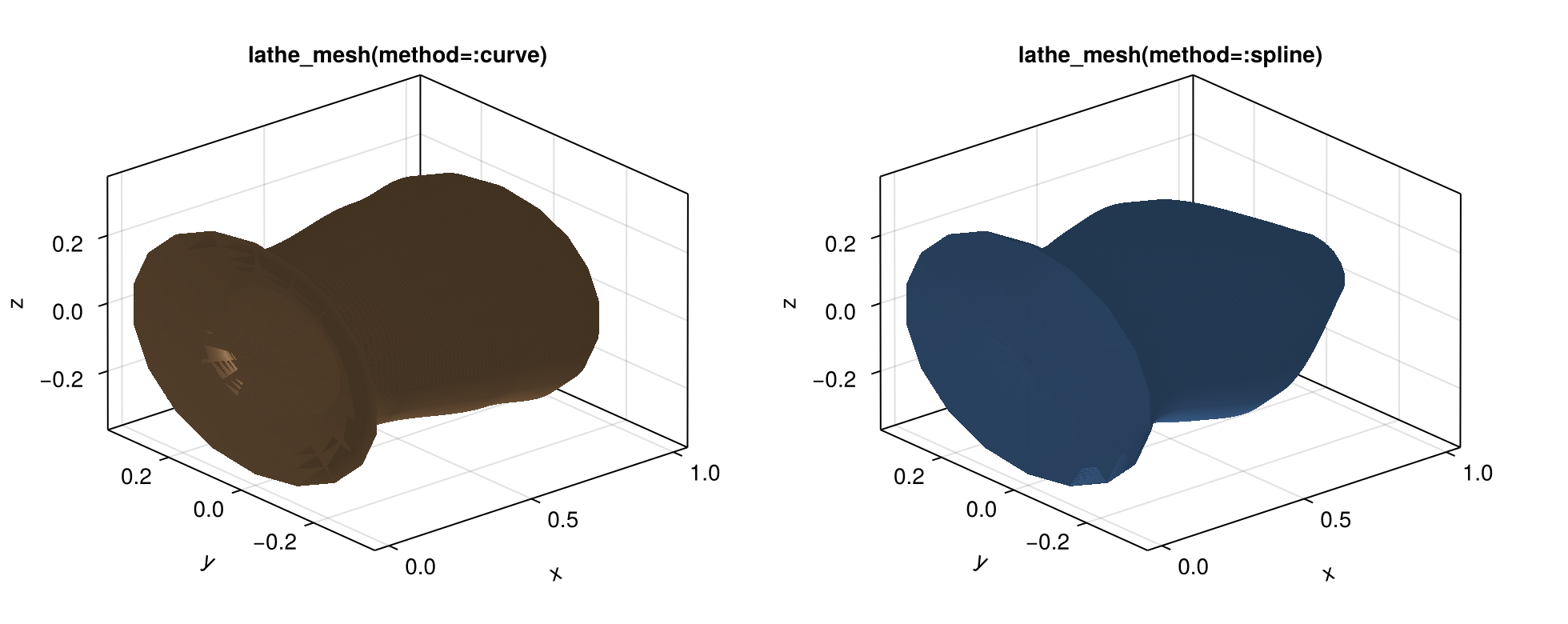
z_samples = collect(range(0.0, 1.0; length=80))
r_samples = [0.31 * (1 - z)^0.85 + 0.02 for z in z_samples]
lathe_gen = lathe_gen_mesh(18, z_samples, r_samples; axis=:x, cap_ends=true)

fig = Figure(size=(520, 380))
ax = Axis3(fig[1, 1], title="lathe_gen_mesh (pre-sampled profile)")
mesh!(ax, lathe_gen, color=RGBA(0.46, 0.36, 0.62, 0.95))
fig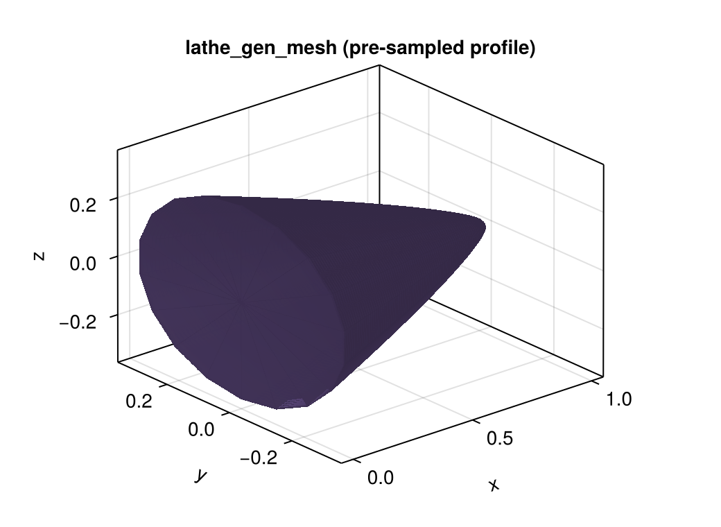
Recommended Pattern
Repeated geometry: use cached procedural
RefMeshconstructors.Unique per-node geometry: use
ExtrudedTubeGeometrydirectly on nodes.In both cases, render with the same
plantvizpipeline.