RefMesh
Page Info
Audience: Intermediate
Prerequisites: basics of
Geometryand reconstruction workflowsTime: 15 minutes
Output: Shared reference-mesh workflows (Level 2 concept page)
This page focuses on shared reference-mesh workflows (RefMesh + Geometry). For the procedural extrusion counterpart (ExtrudedTubeGeometry, extrude_*, lathe_*), see Procedural / Extrusion Geometry. For the high-level attribute-driven realization layer, see Prototype Mesh API. If your main question is "I have one mesh and I just want to place it", start with the manual placement section below.
Reference Mesh Design Philosophy
Most plants contain many similar organs - think of hundreds of leaves on a tree that share the same basic shape but differ in size and orientation. PlantGeom leverages this biological pattern through its reference mesh approach:
Define a single reference mesh for each organ type (e.g., a generic leaf shape)
Apply transformations (scaling, rotation, translation) to position each instance
This approach offers significant benefits:
Memory efficiency: Store one mesh instead of hundreds of copies
Smaller file sizes: OPF files store only unique reference meshes plus transformations
Performance: Operations can be applied to reference meshes once rather than to many instances
For highly specialized shapes that can't be derived from a reference (like wheat leaves with complex curvatures), PlantGeom can still use direct mesh representations.
Where RefMesh fits in the API
RefMesh is the shared geometry asset in PlantGeom.
It is not the same thing as a prototype:
RefMeshstores one canonical mesh plus metadataa prototype tells PlantGeom how to realize node geometry from that asset and from node attributes
This means:
use
RefMeshwhen you want to create, inspect, cache, import, or manually attach shared mesh assetsuse the
Prototype Mesh APIwhen you want PlantGeom to turnLength,Width,Thickness, and other node attributes into final geometry automatically
Quick chooser
| If you want to... | Use |
|---|---|
| Reuse one mesh asset manually with your own transforms | RefMesh + Geometry |
| Build a shared organ asset once and cache it | RefMesh |
| Assign one geometry to one node for debugging | RefMesh + Geometry |
| Rebuild many nodes automatically from MTG attributes | a prototype built from a RefMesh |
| Keep an imported mesh exactly as-is during reconstruction | RawMeshPrototype |
Minimal comparison
Manual / low-level:
mtg_compare = Node(NodeMTG(:/, :Plant, 1, 1))
manual_leaf = Node(mtg_compare, NodeMTG(:/, :Leaf, 1, 2))

manual_leaf[:geometry] = PlantGeom.Geometry(
    ref_mesh=leaf_refmesh,
    transformation=pose(
        rotate=(z=45.0,),
        at=(0.0, 0.0, 0.8),
        deg=true,
    ),
)

plantviz(mtg_compare)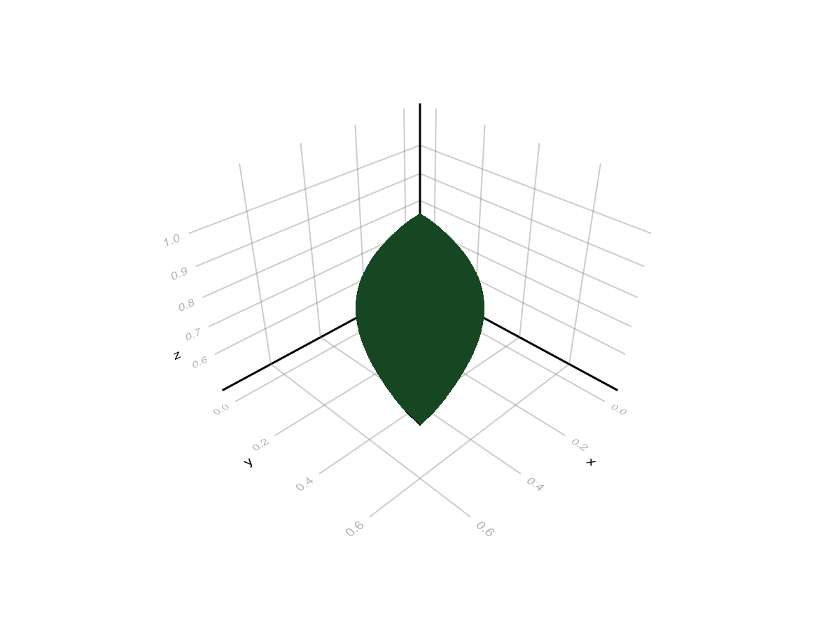
High-level / attribute-driven:
prototypes = Dict(
    :Leaf => RefMeshPrototype(leaf_refmesh),
)

mtg_proto = Node(NodeMTG(:/, :Plant, 2, 1))
leaf_proto = Node(mtg_proto, NodeMTG(:/, :Leaf, 1, 2))
leaf_proto[:Length] = 1.1
leaf_proto[:Width] = 0.30
leaf_proto[:Thickness] = 0.03
leaf_proto[:ZEuler] = -20.0
leaf_proto[:zz] = 0.7

set_geometry_from_attributes!(mtg_proto, prototypes)
plantviz(mtg_proto)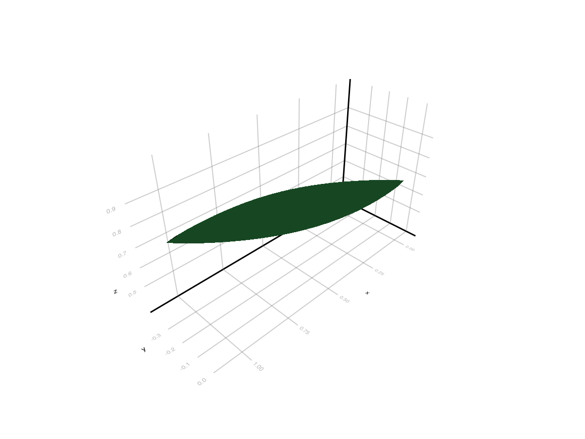
Both are valid, but they solve different problems:
the first gives you total manual control
the second lets PlantGeom realize many node instances consistently from attributes
Overview
RefMesh is PlantGeom's reference geometry container. It stores one canonical mesh plus metadata (material, normals, optional UVs). Node geometries then reuse the same reference mesh with per-node transformations.
This is why RefMesh remains the right low-level building block even now that PlantGeom also has prototypes:
a
RefMeshstays immutable and shareablemany nodes can point to the same mesh asset
you can use the same
RefMeshdirectly in manual geometry or wrap it later in aRefMeshPrototype
Structure
A RefMesh contains:
name: reference mesh name.mesh:GeometryBasics.Mesh(triangular mesh).normals,texture_coords,material,tapermetadata.
MTG Integration
Geometries in PlantGeom are attached to nodes in a Multi-scale Tree Graph (MTG) that represents plant topology:
node = Node(NodeMTG(:/, :Plant, 10, 1))
child = Node(node, NodeMTG(:/, :Leaf, 10, 2))

# Attaching geometry to an MTG node
child.geometry = PlantGeom.Geometry(
    ref_mesh=cylinder_refmesh,
    transformation=pose(at=(0.0, 0.0, 0.4)),
)

(geometry_type=typeof(child[:geometry]),)
(geometry_type = PlantGeom.Geometry{RefMesh{String, GeometryBasics.Mesh{3, Float64, GeometryBasics.NgonFace{3, GeometryBasics.OffsetInteger{-1, UInt32}}, (:position,), Tuple{Vector{Point{3, Float64}}}, Vector{GeometryBasics.NgonFace{3, GeometryBasics.OffsetInteger{-1, UInt32}}}}, ColorTypes.RGB{Float64}, Vector{Vec{3, Float64}}, Nothing}, CoordinateTransformations.Translation{StaticArraysCore.SVector{3, Float64}}, Float64},)This is the direct/manual path. If instead you want the MTG attributes themselves to drive geometry realization, keep the RefMesh as the asset and wrap it in a prototype during reconstruction.
Create a RefMesh
From Vertices and Faces
mesh_vertices = [
    Point(0.0, 0.0, 0.0),
    Point(1.0, 0.0, 0.0),
    Point(1.0, 1.0, 0.0),
    Point(0.0, 1.0, 0.0),
]

mesh_faces = [
    Tri(1, 2, 3),
    Tri(1, 3, 4),
]

plane = GeometryBasics.Mesh(mesh_vertices, mesh_faces)
ref_mesh = RefMesh("plane", plane, RGB(0.2, 0.7, 0.3))
plantviz(ref_mesh)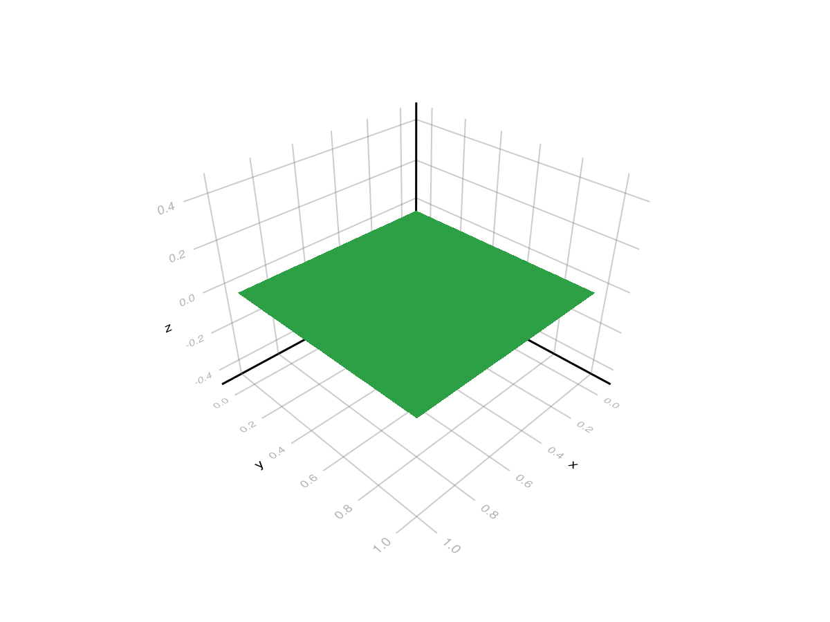
Rotate, Scale, and Place a Hand-Made Mesh
Once you have a RefMesh, the usual manual workflow is:
keep the mesh in local coordinates
attach it to a node with
PlantGeom.Geometryplace it with
pose
pose is the recommended helper for hand-authored meshes because it fixes the transform order:
scale
rotate around local
xrotate around local
yrotate around local
ztranslate
mtg_manual = Node(NodeMTG(:/, :Plant, 1, 1))
panel_node = Node(mtg_manual, NodeMTG(:/, :Panel, 1, 2))

panel_node[:geometry] = PlantGeom.Geometry(
    ref_mesh=ref_mesh,
    transformation=pose(
        scale=(1.8, 0.9, 1.0),
        rotate=(x=65.0, z=18.0),
        at=(0.0, 0.0, 0.6),
        deg=true,
    ),
)

plantviz(mtg_manual)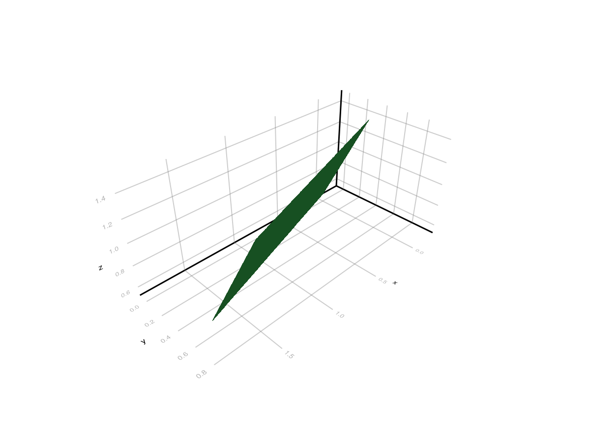
If you need full low-level control, you can still use Translation, LinearMap, AngleAxis, and explicit composition directly.
From a Generated Mesh
sphere_mesh = GeometryBasics.mesh(GeometryBasics.Sphere(Point(0.0, 0.0, 0.0), 1.0))

sphere_refmesh = RefMesh("sphere", sphere_mesh, RGB(0.7, 0.4, 0.3))
plantviz(sphere_refmesh)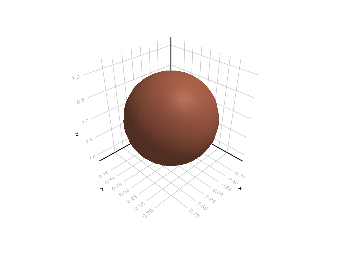
From AMAP-Style Extrusion (Leaflet/Midrib)
PlantGeom includes an AMAP-style extrusion helper (section profile swept along a path), inspired by AMAPStudio's ExtrudeData/ExtrudedMesh pattern.
leaflet_section = leaflet_midrib_profile(; lamina_angle_deg=40.0, scale=0.5)
leaflet_path = [
    Point(0.0, 0.0, 0.0),
    Point(0.3, 0.0, 0.05),
    Point(0.7, 0.0, 0.10),
    Point(1.0, 0.0, 0.12),
]

leaflet_refmesh = extrude_profile_refmesh(
    "leaflet_extruded",
    leaflet_section,
    leaflet_path;
    widths=[1.0, 0.9, 0.7, 0.45],
    heights=[1.0, 1.0, 0.9, 0.75],
    torsion=true,
    close_section=false,
    cap_ends=false,
    material=RGB(0.15, 0.55, 0.25),
)

plantviz(leaflet_refmesh)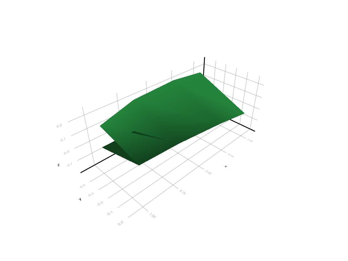
Circular Tube Helper (makeCircle-style)
For axis-like organs, use the dedicated circular section helper:
tube_path = [
    Point(0.0, 0.0, 0.0),
    Point(0.3, 0.05, 0.02),
    Point(0.7, 0.08, 0.05),
    Point(1.0, 0.10, 0.08),
]

tube_mesh = extrude_tube_mesh(
    tube_path;
    n_sides=10,
    radius=0.5,
    radii=[1.0, 0.85, 0.7, 0.55], # taper
    torsion=true,
    cap_ends=true,
)
tube_refmesh = RefMesh("tube_extruded", tube_mesh, RGB(0.55, 0.45, 0.35))

plantviz(tube_refmesh)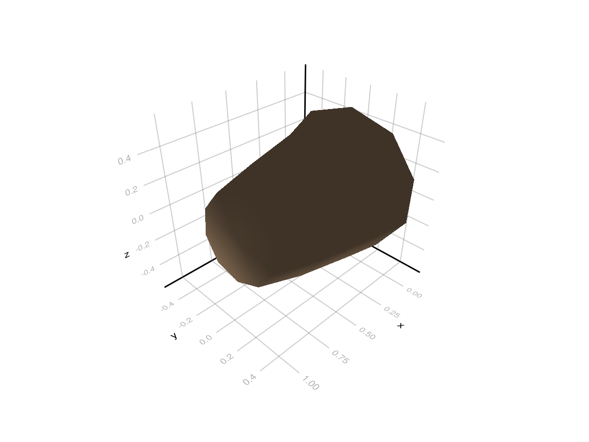
Path Interpolation Helpers (makePath / makeSpline)
These helpers mirror AMAPStudio utilities and are useful to build smooth centerlines before extrusion:
key_points = [
    Point(0.0, 0.0, 0.0),
    Point(0.2, 0.1, 0.05),
    Point(0.6, 0.15, 0.10),
    Point(1.0, 0.0, 0.15),
]

path_hermite = extrusion_make_path(30, key_points)
path_spline = extrusion_make_spline(30, key_points)

(
    n_path_hermite=length(path_hermite),
    n_path_spline=length(path_spline),
)
(n_path_hermite = 31, n_path_spline = 31)Lathe Helpers (latheGen / lathe)
Build axisymmetric reference meshes directly from radial profiles:
z_keys = [0.0, 0.2, 0.6, 1.0]
r_keys = [0.35, 0.25, 0.18, 0.08]

lathe_ref = lathe_refmesh(
    "lathe_profile",
    14,          # around-axis resolution
    40,          # sampling along profile
    z_keys,
    r_keys;
    method=:curve,  # AMAP-like extrema-preserving interpolation
    axis=:x,
    cap_ends=true,
    material=RGB(0.50, 0.38, 0.25),
)

plantviz(lathe_ref)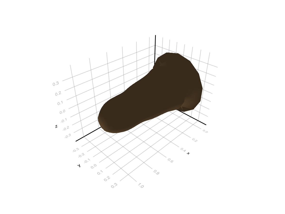
Procedural RefMeshes and Caching
For reconstruction pipelines, do not rebuild procedural meshes for every node. Keep the same pattern as classic OPF refmeshes: build once, then reuse with node transforms.
Use a small cache keyed by your geometry parameters:
cache = Dict{Any,RefMesh}()
key = (:shaft_r04_l10, 12, 0.4, true)

shaft_ref = get!(cache, key) do
    mesh = extrude_tube_mesh(
        [Point(0.0, 0.0, 0.0), Point(1.0, 0.0, 0.0)];
        n_sides=12,
        radius=0.4,
        cap_ends=true,
    )
    RefMesh("shaft_r04_l10", mesh, RGB(0.55, 0.45, 0.35))
end

# same key => same RefMesh instance reused
shaft_ref_again = cache[key]

shaft_ref === shaft_ref_againtrueRecommended integration rule:
when many nodes share the same procedural shape parameters: use cached constructors and reuse the
RefMeshwhen each node has unique geometry (for example organ-specific measured profile): build one
RefMeshper unique parameter setkeep node placement in
Geometrytransforms (translation/rotation/scale) as usual
Procedural Node Geometry (Without RefMesh)
If each node has its own geometry parameters, you can assign a procedural geometry object directly to node[:geometry].
ExtrudedTubeGeometry is the first concrete type for that workflow. It is built on demand by the same scene merge/render pipeline used for classic Geometry.
mtg_proc = Node(NodeMTG(:/, :Plant, 1, 1))
stem = Node(mtg_proc, NodeMTG(:/, :Internode, 1, 2))
tube = Node(mtg_proc, NodeMTG(:/, :Internode, 2, 2))

stem[:geometry] = PlantGeom.Geometry(
    ref_mesh=RefMesh(
        "stem_ref",
        GeometryBasics.mesh(GeometryBasics.Cylinder(Point(0.0, 0.0, 0.0), Point(1.0, 0.0, 0.0), 0.06)),
        RGB(0.55, 0.45, 0.35),
    ),
)

tube[:geometry] = ExtrudedTubeGeometry(
    [
        Point(0.0, 0.0, 0.0),
        Point(0.2, 0.03, 0.00),
        Point(0.4, 0.08, 0.01),
        Point(0.7, 0.14, 0.03),
        Point(1.0, 0.18, 0.05),
        Point(1.2, 0.20, 0.06),
    ];
    n_sides=18,
    radius=0.05,
    radii=[1.0, 0.95, 0.88, 0.80, 0.72, 0.65],
    torsion=false,
    cap_ends=true,
    material=RGB(0.35, 0.50, 0.70),
    transformation=pose(at=(1.25, 0.0, 0.0)),
)

plantviz(mtg_proc)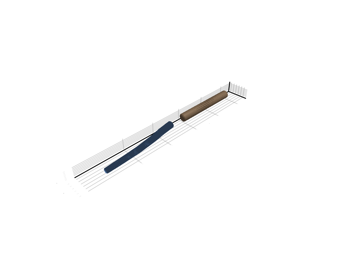
Cylinder-like Primitive
plantviz(cylinder_refmesh)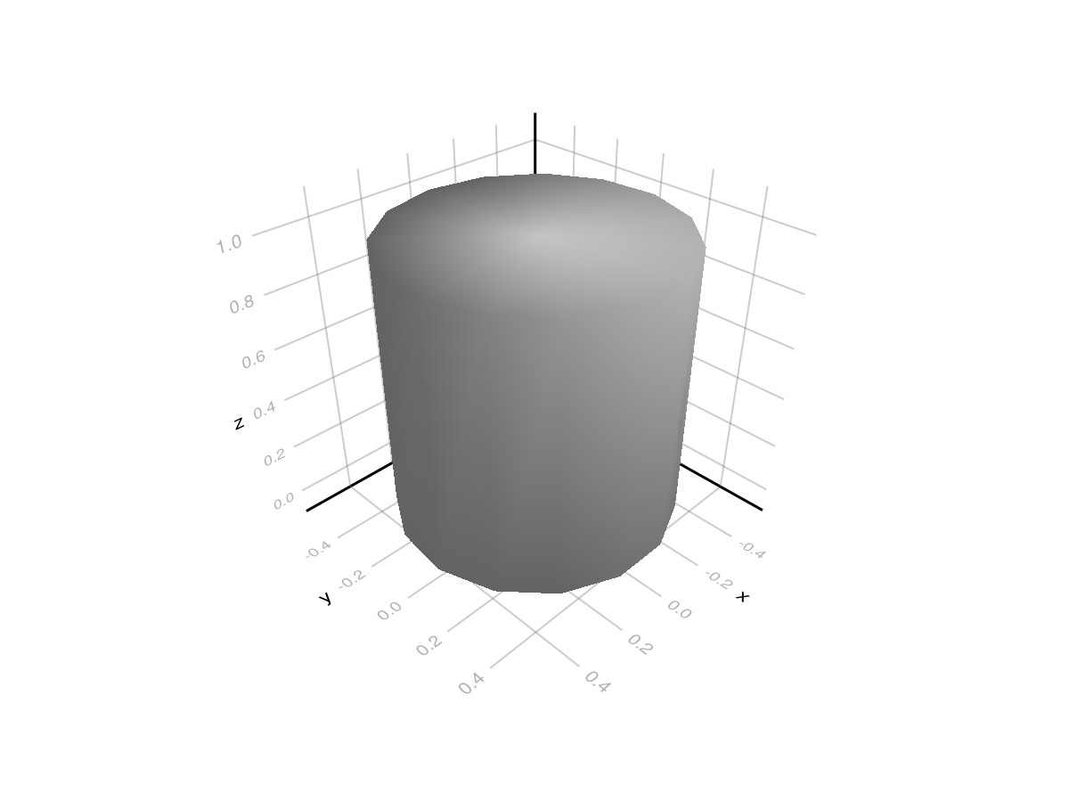
Access Properties
(name=cylinder_refmesh.name,
 nvertices=nvertices(cylinder_refmesh),
 nelements=nelements(cylinder_refmesh))
(name = "cylinder_1", nvertices = 32, nelements = 60)Meshes.jl Interop
PlantGeom's core backend is GeometryBasics, but you can build meshes in Meshes.jl and convert them using the optional extension API:
to_geometrybasics(mesh::Meshes.SimpleMesh)to_meshes(mesh::GeometryBasics.Mesh)to_meshes(ref_mesh::RefMesh)
Build a RefMesh from Meshes.jl
using Meshes

mesh_meshes = Meshes.CylinderSurface(
    Meshes.Point(0.0, 0.0, 0.0),
    Meshes.Point(0.0, 0.0, 1.0),
    0.2,
) |> Meshes.discretize |> Meshes.simplexify

mesh_gb = to_geometrybasics(mesh_meshes)
ref_from_meshes = RefMesh("cylinder_from_meshes", mesh_gb, RGB(0.3, 0.5, 0.8))

plantviz(ref_from_meshes)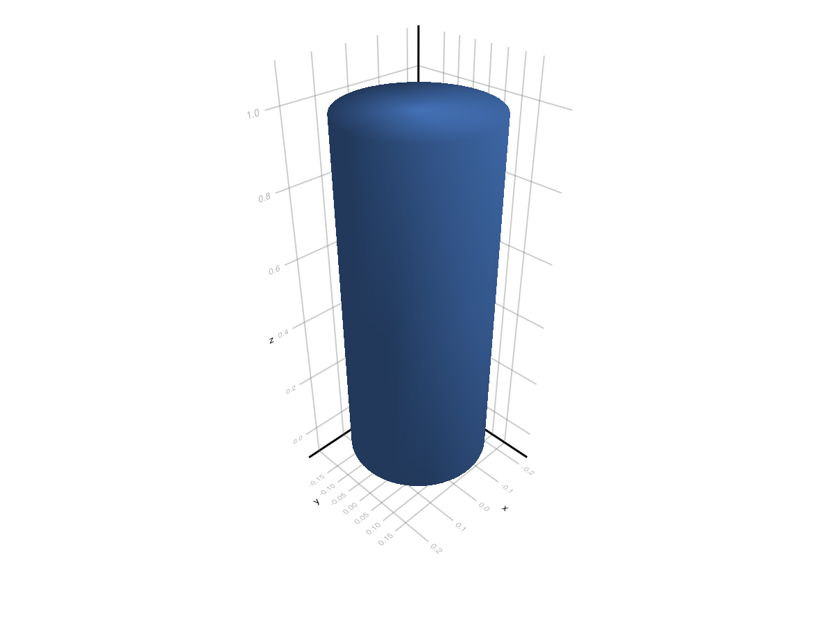
Convert Back to Meshes.jl
mesh_back = to_meshes(ref_from_meshes)
(
    nverts_meshes = length(collect(Meshes.vertices(mesh_back))),
    nfaces_meshes = length(collect(Meshes.elements(Meshes.topology(mesh_back)))),
)
(nverts_meshes = 152, nfaces_meshes = 300)